@RickRay
Yup. Of all the implementation configurations you could have, this is one that you'd most definitely want to use the sense lines (even if a proximal regulator might function adequately -- if not properly -- without it).
In general, though, I'd still want to locate a super" regulator next to the circuit to extract the full benefit without subjecting it to environmental vagaries.. stray fields etc.
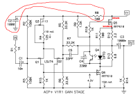
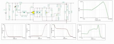
Here is the schematic of the ACP+ headphone amp, which member @tamra is connecting to his Super Regulator in post #3,176. Please calculate / explain how much this amplifier will benefit if you lower it's power supply output impedance from 19 millliohms (without remote voltage sensing) to 13 microohms (with remote voltage sensing).
19 milliohms = go-and-return resistance of 6 feet of AWG-22 copper wire (in the umbilical cable)
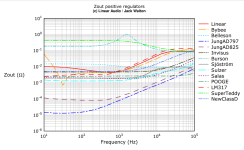
13 microohms = measured Zout of Super Regulator with remote sensing, from Linear Audio (attached below)
_
19 milliohms = go-and-return resistance of 6 feet of AWG-22 copper wire (in the umbilical cable)
13 microohms = measured Zout of Super Regulator with remote sensing, from Linear Audio (attached below)
_
Attachments

Because you didn't ask for it. Duh.I can show you the Google page I opened, and no one mentioned any models availability. No laziness involved.
Mark did.
Jan
I think "Linear" refers to the LT1963, not the Jung-Didden variety. (btw, the LT1963 sounded great). You can get the AD797 variety down into the very low uOhms but it is very "ttchy" with respect to stability.Here is the schematic of the ACP+ headphone amp, which member @tamra is connecting to his Super Regulator in post #3,176. Please calculate / explain how much this amplifier will benefit if you lower it's power supply output impedance from 19 millliohms (without remote voltage sensing) to 13 microohms (with remote voltage sensing).
19 milliohms = go-and-return resistance of 6 feet of AWG-22 copper wire (in the umbilical cable)
13 microohms = measured Zout of Super Regulator with remote sensing, from Linear Audio (attached below)
_
Zout is a wonderful target, but not particularly relevant to the application at hand as you correctly point out!
@jan.didden
Hi Jan and thanks for coming back to support us! And so I have a quick question for you")
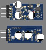
I've built a SR for USB. The problem with USB Audio is that it runs at 240MHz and any power supply imperfection at this frequency causes an audible jitter. I've tried a number of opamps and higher frequency ones (plus low noise) sound best. I've also tried a few voltage references. The best sound in my setup is with the serial reference LTC6655LN (2.5V). The problem is that this reference doesn't start when is fed from the output of the regulator, so I feed it from the input. This is alright, because I feed this regulator by another Super Regulator, so the input is clean and I feed the opamp from the input as well. The result sounds fantastic in my setup, light years ahead of the default circuit.
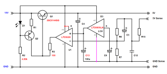
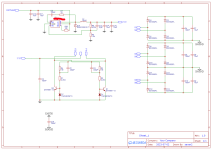
Please forgive if my question is silly, as I am not a designer by any stretch. Where should I connect the ground of the voltage reference (the pink line on the attached schematics), to the ground sense as shown or to the actual ground? Thanks so much for your help!
To explain the changes, R4 is 300 Ohm and is inside the voltage reference chip connected to C9 at pin 6. Pin 8 of the opamp is connected to the power to cancel the output voltage error due to the input bias current. R3 is 100 Ohm to stabilize this opamp, which otherwise oscillates. C13 is low ESR to stabilize the voltage reference and further reduce its noise. Not shown values are default, not shown parts are removed. All part numbers match your original schematics (except for the addition of C13).
Alex
Hi Jan and thanks for coming back to support us! And so I have a quick question for you
I've built a SR for USB. The problem with USB Audio is that it runs at 240MHz and any power supply imperfection at this frequency causes an audible jitter. I've tried a number of opamps and higher frequency ones (plus low noise) sound best. I've also tried a few voltage references. The best sound in my setup is with the serial reference LTC6655LN (2.5V). The problem is that this reference doesn't start when is fed from the output of the regulator, so I feed it from the input. This is alright, because I feed this regulator by another Super Regulator, so the input is clean and I feed the opamp from the input as well. The result sounds fantastic in my setup, light years ahead of the default circuit.
Please forgive if my question is silly, as I am not a designer by any stretch. Where should I connect the ground of the voltage reference (the pink line on the attached schematics), to the ground sense as shown or to the actual ground? Thanks so much for your help!
To explain the changes, R4 is 300 Ohm and is inside the voltage reference chip connected to C9 at pin 6. Pin 8 of the opamp is connected to the power to cancel the output voltage error due to the input bias current. R3 is 100 Ohm to stabilize this opamp, which otherwise oscillates. C13 is low ESR to stabilize the voltage reference and further reduce its noise. Not shown values are default, not shown parts are removed. All part numbers match your original schematics (except for the addition of C13).
Alex
Attachments
For those who need upgraded version of the mini J.Didden regulators, material for making them is in attachment.
+5V version is the same as HPR15 but with few changes (SA5534 is replaced with OPA209, AZ431 is replaced with LMV431, zener diode is replaced with 2.4V, the rest is the same except resisitor divider which I didn't had time to calculate since on picture 3 there is simulation with J113 but our pcb from attachment don't use J113, if you need +5V do it yourself). Enjoy!
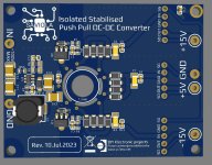
If you need simple and amazing self-resonating isolated push pull pre-regulator here is schematic too, pcb 65x50mm of the push pull for our J.D. regulators is closed source sorry! Ferite is Ferroxcube TN10/6-3E25 10,6x5,2x4,4 mm , AL 2250nH, twenty turns of copper varnished wire per coil.
+5V version is the same as HPR15 but with few changes (SA5534 is replaced with OPA209, AZ431 is replaced with LMV431, zener diode is replaced with 2.4V, the rest is the same except resisitor divider which I didn't had time to calculate since on picture 3 there is simulation with J113 but our pcb from attachment don't use J113, if you need +5V do it yourself). Enjoy!
If you need simple and amazing self-resonating isolated push pull pre-regulator here is schematic too, pcb 65x50mm of the push pull for our J.D. regulators is closed source sorry! Ferite is Ferroxcube TN10/6-3E25 10,6x5,2x4,4 mm , AL 2250nH, twenty turns of copper varnished wire per coil.
Attachments
Last edited:
@jan.didden
I think it should be to the ground sense as shown, because the opamp is comparing voltages relative to the ground sense while the source of the power supply for the reference is irrelevant. Could you please confirm if my thinking is correct? Thank you!
Out of 9 SR boards I've bought from the diyAudio Store, I've used 3 so far for USB. My next project is a +/-18V SR for a phono preamp.
Please forgive if my question is silly, as I am not a designer by any stretch. Where should I connect the ground of the voltage reference (the pink line on the attached schematics), to the ground sense as shown or to the actual ground? Thanks so much for your help!
I think it should be to the ground sense as shown, because the opamp is comparing voltages relative to the ground sense while the source of the power supply for the reference is irrelevant. Could you please confirm if my thinking is correct? Thank you!
Out of 9 SR boards I've bought from the diyAudio Store, I've used 3 so far for USB. My next project is a +/-18V SR for a phono preamp.
I am still using boards from Old Colony, and two from the diyAudio Store!Out of 9 SR boards I've bought from the diyAudio Store, I've used 3 so far for USB. My next project is a +/-18V SR for a phono preamp.
What phono preamp is that?
Aria by Rega, the original first model.
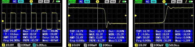
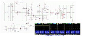
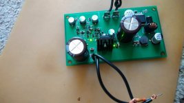
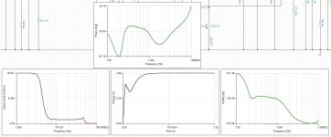
The first preliminary test, this is fully discrete 5V J.D. regulator, I have found that led diode with 2V VF as used here in test is not a good choice, need to find better one with 1.5V FV or with smaler one VF, which one you reccomend with size 0603? The bad choice used in this test is https://www.lcsc.com/product-detail/Light-Emitting-Diodes-LED_Lite-On-LTST-C191KGKT_C125098.html and this is a results from regulator which is not that bad at all? I will revide mini J.D. from post 3195 , its simulated with wrong diode! Also L4 must be removed, cause oscilations! Simulation result picture 3. Phase and PSRR is a lot better with VF=1.5V led diode,, if you know which one is perfect for this and have size 0603 please let me know!
Attachments
Last edited:
- Home
- The diyAudio Store
- Super Regulator