I think 3V and 3.3V is important to many users.
So how about this:
Low voltage version (2.5V ref): start at 2.5V, end at 12V
High voltage version (6.9V ref): start at 7V, end at 24V
Very high voltage version (10V ref): start at 12V, end at 36V.
That should cover it all.
If you can get that in one document, with your name/email as author if you want, I'll get it in the webpage.
Jan
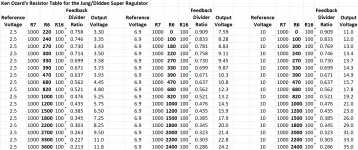
Please take a look at this draft and please let me know what to edit/adjust. Please let me know if you think R6 = 0 is a bad idea. (There is still the 100 Ohm in the feedback filter.)
I included some E24 resistor values to get closer to common voltages.
I included some E24 resistor values to get closer to common voltages.
Attachments
Last edited:
I think you should leave R6 = 100R in, it is there.
1st column, include 3V as a start, some equipment needs that, no need to stop at 12V exactly as the 12V setting will be in the other column.
2dn column, start at 7V, there are some opamps that work off +/-7V.
3rd column, make sure to end at 36V, which I am asked about often.
Otherwise looks fine.
Edit: be sure to include rounded outputs like 3V, 3.3V, 5V, 7V, 8V, 12V, 15V, 18V, 24V, 28V, 36V. That is what I see people asking for.
Limiting the chart to only these values may be enough.
Jan
Last edited:
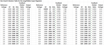
I would not do that, it confuses people, it gets forgotten and it changes the compensation.
I see that you vary R6 and then compute Vo. It should be better to vary Vo, set the required Vo, then compute R6.
Then you can give the exact R6 and the closest E96 and the actual Vo with that closest value.
A bit more work but much more useful.
What do you think?
Jan
I see that you vary R6 and then compute Vo. It should be better to vary Vo, set the required Vo, then compute R6.
Then you can give the exact R6 and the closest E96 and the actual Vo with that closest value.
A bit more work but much more useful.
What do you think?
Jan
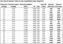
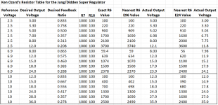
Ok. See attached.
Hopefully component tolerance will be understood.
Ken, this is perfect! Thank you very much. I'll get it posted at the website.
Yes, resistor tolerances are always there, but it should be understood that a nominal +/-15V supply never is exactly +/-15V. Anything between 14.8 and 15.2 is fine. 1% resistors almost always are fine.
Thanks again,
Jan
would a shunt resistor at the base of the pass transistor of value say between 2,2k-4,7k help to speed up its response ? I am building from scratch a 2,5A/18V +/- dual rail with big 150W bipolars. Highish beta 120 allows me to cover whole regulation from just op-amp without darlingtons.
at predicted 2,5A Iq (2,3A for the JLH1996 and 0,2A for the shunt resistor), these are about 63 Mhz fast:
https://www.onsemi.com/pdf/datasheet/njw3281-d.pdf
i have 7V voltage offset on them, mere 200mV rather sinusoidal ripple from CLC.
Measured temperature in the thermal grease right at the middle leg after 30 minute operation is now 100 C, but heatsinks are now too small. Temperature will be lower once pass transistors get integrated with the JLH amplifier.
beta of 120 and 40 mA current capability of AD797 covers whole regulation.
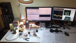
as for now, i have a cable-salad on the table, loose connections in prototype breadboards, horrendous inductances, and still my 30 Mhz oscillocope sees only random noise at 20Mhz with 2,3 A load. Should get better once it all gets soldered together with milimiter long tracesl
https://www.onsemi.com/pdf/datasheet/njw3281-d.pdf
i have 7V voltage offset on them, mere 200mV rather sinusoidal ripple from CLC.
Measured temperature in the thermal grease right at the middle leg after 30 minute operation is now 100 C, but heatsinks are now too small. Temperature will be lower once pass transistors get integrated with the JLH amplifier.
beta of 120 and 40 mA current capability of AD797 covers whole regulation.
as for now, i have a cable-salad on the table, loose connections in prototype breadboards, horrendous inductances, and still my 30 Mhz oscillocope sees only random noise at 20Mhz with 2,3 A load. Should get better once it all gets soldered together with milimiter long tracesl
Attachments
Last edited:
- Home
- The diyAudio Store
- Super Regulator