Farnell is back order for international, and their site always breaks on me at check out. I gave up on them years ago.
RS for USA or Canada does not even list Alps potentiometers, and has no shipping options for the overseas options I tried.
I think maybe the best thing is to replace the pot with a header. This will give me more flexibility for board placement, and let me swap different pots in and out.
Any special considerations for the wire? I have some shielded 8 conductor 18ga twisted signal wire I used when I added speed control, tach, etc to my 3phase lathe.
I could also chop up a HDMI cable for some better wire.
Thanks
-Josh
No special wire recommendations, use whatever extension is practical to you
- Sorry, *please* forgive me. I looked over the board when I received it and it looked identical to the board shot on the DIY store. They are close, but there are subtle differences; so mine does have the power LED designation like your attached picture does (when the store picture doesn't).
Thanks a lot for the help!
So I think I've settled on the EAO 82-series switch (model# 82-5151.2123); it feels the best of the three I ordered. According to the spec sheet it also does have a series resistor in place; the manufacturer recommends 7mA of current. (See attached.) So in theory, I just short out the 2.2k resistor near the PWR LED and wire the switch up directly? Are there any tests I could/should run with a multimeter (or whatever else) beforehand so I don't accidentally burn it up?
Thanks again. I've got all my parts ordered minus the chassis. I'm getting excited to put this together!
Btw, are there any videos of someone putting one of these together? I've never made a video before, but maybe it'd be helpful for others if I did.
Attachments
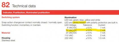
Hello, I don't think there are any construction videos. Yes, if it has independent pins for that you short out the 2.2K and you wire from the pwr led position which effectively becomes a 12VDC outlet. Unless it steals current internally from what it switches. If you have a lab supply set it at 10mA CC mode (current limit protection) and 12V DC to test it in safety on its + - illumination pins.
@Salas Thanks for all the help so far! I'm very near to putting this all together. I might buy a lighting setup to get a good video of the build; just seeing if the wallet will allow it.
A few questions regarding the layout (#1-3, see highlighted sections in 1st image) & additional questions (#4-6)...


Thanks again as always.
A few questions regarding the layout (#1-3, see highlighted sections in 1st image) & additional questions (#4-6)...
- Do I just jumper/short this section (like the jumper between the MUR120s)?
- What's this for? For verifying the voltages? If so, does it go top to bottom: V-, G, V+?
- This is the vertically mounted resistor, correct?
- Is there any benefit to upgrading the 100uF caps with something like UKZ1E101MPM (I believe the original BOM said 25V caps was sufficient) or UKZ1H101MHM?
- The two heat sinks are for the 9240s, correct? What's the method to attach the HS to the chassis? (Sorry, I'm new to all this.)
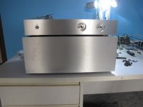
- Alternatively, in someone else's build, looks like they mounted the 9240s on the chassis floor (see 2nd attachment below). Additionally, it looks like they even used wires as an extension. Will this degrade the audio quality?
Thanks again as always.
@gwolfman
1. Its an already connected section in dual layer Mezmerize blue boards (not in legacy single layer black boards) but its reinforcement with wire jumper is also welcome. That portion is the ground lane's thinnest travel section.
2. Yes, its mainly for verifying voltages. Or to tap off regulated DC for low consumption utility circuits, but not recommended to do that if not having the instruments to check that no interference has been introduced on the rails.
Also, in older days before I had general use shunt PSU projects out there (SSLV1.1_BiB/SSLV1.3_UltraBiB) some people used the Mez board for its shunt PSU section alone to power other projects. They liked this shunt PSU's character in many apps, not for what it brings to the Mez only. Few left hand side signal select and JFET buffer major board areas simply got hacked off and ended up in the bin back then...
3. Correct
4. Subjective area. If keen for detail you may replace types there, then listen to your system's synergy in personal taste and decide. Yes, 25V is enough for the 100uF caps. If you have good rework skills and tools it can be a very easy and clean swapping job. Or you can put small female pins while using cut to short legs various capacitors for listening back and forth with until you decide. Mind you that's a sure recipe for developing audiophilia nevroza
5. Absolutely essential to insulate the MOSFETS for sinking in common metal between them. Else kaboom! You need TO-247 sized insulator pads as listed in the 2018 BOM or alike. Not insulated screws and nuts though because such type MOSFET cases already offer an insulated mounting eye area. In the end you better test your assembly work for there is no continuity beep with a DMM's special test mode for shorts, when touching the probes between a conductive chassis point and each MOSFET's middle pin successively (do that before powering on).
6. A substantial chassis is also good for sinking this project, (run as BOM standard), instead of dedicated sinks. If must have MOSFET pin extensions, not obvious degradation occurs before the length of extension wires passes a critical point and PSU oscillation appears. Wire self inductance is not good news there, although this design has some degree of tolerance in matters practical, its not meant to be abused either. If you have no oscilloscope and experience in its use to verify the rails are clean from oscillation, better don't modify with extension wires when avoidable.
...
Also,
The Alps pots are pretty much unobtainium in the US it seems from reputable dealers.
Plenty of them on Ebay, made in Japan - ships from China...
Mouser sells 100K ones, they list exactly 1 10K pot, but it is really a 100K according to the spec sheet.
I ordered what may be a fake from a US seller. Will let every one know what it looks like it gets here.
I have found the RK27112A00A6 20 kΩ Log at Newark/element13 for $15.33.
I have found the RK27112A00A6 20 kΩ Log at Newark/element13 for $15.33.
Thanks.
The Ebay item I got actually seemed to be authentic. If it is a forgery, it is a good one - free shipping too
ORIGINAL & Brand New ALPS RK27 27 Type Dual 10K 10KA X 2 Potentiometer US Seller | eBay
I actually prefer moving the pot off the board so I can swap pots in and out, or try something like a lightspeed. It also gives me flexibility in terms of board placement.
Changes:
1.
The mounting distances are now compatible with perforated bottom plates of the Italian chassis
line that the diyA online store carries (mechanical change)
2.
The five LEDS +/- voltage reference chains in the PSUs now work with equal current bias like
in the vintage Hypnotize hot-rod version (layout level schematic point change)
Decided to use this case for mine, should go well with the M2X.
Full Aluminum Amplifier Chassis Amp Enclosure Preamp Box 425*70*313mm | eBay
I will need to drill a few more holes for the other 2 input channels, I really like the idea that it has the shielded compartment for the PSU.
Full Aluminum Amplifier Chassis Amp Enclosure Preamp Box 425*70*313mm | eBay
I will need to drill a few more holes for the other 2 input channels, I really like the idea that it has the shielded compartment for the PSU.
Decided to use this case for mine, should go well with the M2X.
Full Aluminum Amplifier Chassis Amp Enclosure Preamp Box 425*70*313mm | eBay
I will need to drill a few more holes for the other 2 input channels, I really like the idea that it has the shielded compartment for the PSU.
Haha, that's the same case I bought.
I have a couple of questions.
First, how much heat sinking does the Mesmerize need?
I have a 2U Slimline chassis coming this week, and I was wondering if I could mount the B1 on one of the "pseudo" heat sinks. The B1 transformer is an Antek AS1215
The chassis will hold a total 3 transformers, an Allo Katana, and 3 Salas Ultra-BiB power supplies (4 power rails). I would not go so far as to say space is at a premium, but it is a bit tight.
Second, what are people doing for wiring to the output jacks? I am debating between microphone wire, coax, and just braiding the conductors and ground from something like 22ga solid core wire. I will be able to route them away from the transformers and power supplies, I am just not sure about how much I have to worry about EFI in this situation, so I would love to hear the experience and wisdom of others on this subject.
Thanks,
-Josh
2W dissipation per Mosfet i.e. 4W per side. 3mm alu chassis floor will do, not even needing the pseudo heatsink side. Unless you must mount it on the side if it fits. Or 3C/W heatsinks like FISCHER SK 81/ 50 SA, Aavid Thermalloy 0SY76/100/N etc.
I generally recommend coax and there are good quality small diameter microphone style types with two conductors and a shield from trusted manufacturers like Mogami etc.
I generally recommend coax and there are good quality small diameter microphone style types with two conductors and a shield from trusted manufacturers like Mogami etc.
Not sure if this is possible or not, I was thinking of adding a second pair of output connectors in parallel with the originals so I can connect to my WHAMMY, is there anything I need to put between the 2 outputs or can I just connect wires between the 2 pairs of RCA connectors.
Cheers
Cheers
- Home
- The diyAudio Store
- Mezmerize B1 Buffer Preamp