I think the open baffle is out of the running, for a couple of reasons. Even with a very large baffle, it just doesn't seem like an effective way to get as low as I want; and the second row of seating is at the bar, which is right where the front and back waves interact.
I am leaning towards the transmission line, but it looks like that's going to result in an underdamped system with an infrasonic FR peak. Can I effectively mitigate that issue with stuffing (Hornresp tells me I can with very little stuffing near the terminus, at least as far as the FR peak is concerned), and does it actually matter?
I am leaning towards the transmission line, but it looks like that's going to result in an underdamped system with an infrasonic FR peak. Can I effectively mitigate that issue with stuffing (Hornresp tells me I can with very little stuffing near the terminus, at least as far as the FR peak is concerned), and does it actually matter?
Here are plots of damping in a labyrinth. The impedance plot roughly translates into cone motion. You can see the benefits of a long pipe with lots of stuffing, as I said in post #36.
17 foot pipe sub 12-230 Hz ±5dB
B.
17 foot pipe sub 12-230 Hz ±5dB
B.
Last edited:
Jump on the AVS forum, they'll have a topic (or many) on this sub for sure as people buy them by the dozen!
Or ask the owner, Nick from Stereo Integrity what he thinks.
The reason for my reply is that I think you're getting bum steered here which doesn't mean you are, it's just my opinion...
Or ask the owner, Nick from Stereo Integrity what he thinks.
The reason for my reply is that I think you're getting bum steered here which doesn't mean you are, it's just my opinion...
In a tapered (smaller at terminus) TL, how undesirable is it actually to have a little underdamped peak at resonance if the resonance is under 15hz? I can't seem to make that go away due to, I assume, the driver's QTS. I'm not worried about the actual FR peak, or even transient response or some ringing in the infrasonic range. I'm more concerned with what it would mean for the system's behavior an octave or more above the resonance. If the effects above 20hz would be significant, can they be mitigated by lightly stuffing the line near the terminus to squash that peak?
Hmm, done right there shouldn't be one, though if using HR, it doesn't take any inherent acoustic damping into consideration, so if it sims flat it will be over-damped in reality [rolled off].
Yes, it's due to the driver's high effective Qts/Qts': [Qts']: [Qts] + any added series resistance [Rs]: Calculate new Qts with Series Resistor
Regardless,it will depend on its Q, i.e. how 'fast' it decays. In general though, not an issue and yes, it can be damped out in the pipe.
Anyway, a basic 16 Hz TH sim attached.
Attachments
Jump on the AVS forum, they'll have a topic (or many) on this sub for sure as people buy them by the dozen!
Or ask the owner, Nick from Stereo Integrity what he thinks.
The reason for my reply is that I think you're getting bum steered here which doesn't mean you are, it's just my opinion...
In what way? Regardless, always a good plan to see what others are doing, especially the manufacturer
In a tapered (smaller at terminus) TL
FYI/FWIW, IME and proved to my satisfaction when 'proofing' MJK's MathCad design programs against some of my own Tower/Column alignments from 'way back when', the vented TL [closed pipe] alignment [aka MLTL] range from ~0.312 - 0.624 Qts' seems technically good enough, i.e. from Keele's 6th order assisted bass reflex to his Extended Bass Shelf [EBS] alignment.
While the 'sweet spot' [mean] is a ~0.4412 Qts', a 'close enough' simple guideline is:
~0.403, Vb = Vas, Fb = Fs [MLTL]
< ~0.403, Vb = < Vas, Fb = > Fs [inverse tapered MLTQWT]
> ~0.403, Vb = > Vas, Fb = < Fs [expanding taper MLTQWT/MLhorn]
So ideally need a horn taper. The inverse taper can be viewed as a long ducted port [BR] morphed into a ~equivalent net volume [Vb] TQWT, which in turn can be fine tuned using a 'stub' vent [mass loaded = MLTQWT] as needed.
GM, that is some great info, I really appreciate it. I'll take a look at that TH sim later today.
The manufacturer's recomentation for a "S-ULF" bass reflex enclosure is 22ft^3 tuned to 16hz, which looks quite adequate for my purposes. I ordered the drivers with the intention of building something like that if I couldn't come up with a better design, hence this thread.
Your guidelines about the relation between Qts' and optimal taper direction actually make a lot of sense, now that I think about it. I'll convert my contracting TL models to expanding MLTLs and see what happens.
Thanks again. Now I know which direction to focus my efforts.


That TH design is interesting. It's smaller than anything I could get to work that well. The TH is looking like the SPL king of feasible designs, but it would be tricky to fold up, and I think I'm liking the response of the TLs better.
In tinkering with MLTQWT models last night, I think I discovered some adjustability for the Q (and amplitude) of the peak at resonance. It seems that for a given Vb and Fb, increasing the line length (and consequently decreasing the cross section, and making the vent larger/shorter) increases damping. At 600L Vb and 14-15Hz Fb, it even reaches the point where it sims a little over-damped before the mass loading vent goes away completely. So it looks like a good design exists, I just have to find it.
In tinkering with MLTQWT models last night, I think I discovered some adjustability for the Q (and amplitude) of the peak at resonance. It seems that for a given Vb and Fb, increasing the line length (and consequently decreasing the cross section, and making the vent larger/shorter) increases damping. At 600L Vb and 14-15Hz Fb, it even reaches the point where it sims a little over-damped before the mass loading vent goes away completely. So it looks like a good design exists, I just have to find it.
I think I have a decent design for a MLTQWT now, assuming the folds work out. The cross sections are small enough that I'll be able to fold it twice, and it's just short enough that I might not have to, so there should be some flexibility there. It's about 750L, tuned to 14Hz. Hornresp predicts all but 120db down to 12.5Hz at 46 volts (500-ish watts) in 1pi space. It shouldn't reach xmax above 13Hz unless I put over 63v to it. It's looking nice and flat up to about 65Hz where it starts getting peaky, so I might have to tame that with some damping.
I don't expect to have the drivers for at least a month, so I'm sure the design will go through a few more iterations before it's built, but I'm definitely liking this relatively small cross-section MLTQWT concept.
Edit: Of course, it just occurred to me that this thing is hardly mass loaded at all, so I tried removing the vent entirely and extending the taper to arrive at the same tuning. That also looks promising.
Attachments
Last edited:
So I had an idea for this that seems to model like a best-of-most-worlds solution for this driver, but I haven't seen anyone do anything quite like it before. Hopefully somebody can tell me if this makes sense.
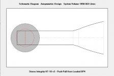
The idea is that I take a sealed PPSL enclosure, and extend the slot into a roughly 35-40 hz horn. Physically it would look like a "W-Bin" FLH, with a sealed chamber, and with the throat extended through the center of the chamber. The sweet spot that I found is a chamber volume around 350 to 500 liters (the model is surprisingly insensitive to this), throat CSA around 1400-2000 cm^2, and mouth CSA around 4000-8000 (total, or roughly 2-4 square feet per side).
This design would end up in the 1000-1500 liter range. The frequency response looks a lot like a sealed box, but with some extra LF extension, a high shoulder somewhere between 100 and 150 (since it's a 4th order bandpass design), and 6-10db of extra gain in the 20-80 hz passband. Phase and group delay behave themselves much better than in a TL or TH, excursion is very well controlled within the power limits of the driver, impulse response looks reasonable. Hornresp is claiming my current amp is enough to get 125 db at 20hz, 115db at 15hz, and hearing damage in the midbass (in 1pi space; one of the horn mouths will be near a wall, and both will be firing into the back of the seats, so I think using 1pi should be conservative enough, though I remain skeptical of the actual SPL numbers; 135db at 40hz with 1000 watts just seems like an awful lot).
I'll post my sims later when I can. Does anyone see any problems with the concept? I know FLHs not too unlike this have been done plenty of times before, but typically they're using drivers with higher fs and lower qts, and arriving at a somewhat higher passband.
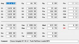
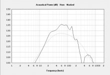
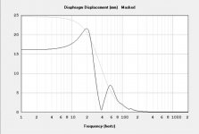
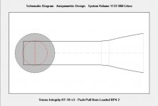
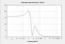
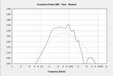
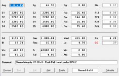
Here's the Hornresp info for one version. The lighter line in the SPL and displacement graphs is a 1200 liter sealed enclosure with two of the same driver.
Attachments
Here's another iteration. Bigger pipe, smaller mouth, flatter response, a little trickier to fit the pipe around the drivers.
Attachments
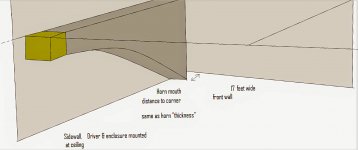
A horn enclosure I'd been contemplating for awhile. This would take advantage of a truly large & proportional main living room.
Imagine if you will a pair of large rectangular "boxes" mounted up in the rear corners of your listening room...a sweeping horn that terminates at the "front" of the room...the front corners functioning as a continuation of said horn.
One could incorporate shelving & cabinetry within the open curvature to disguise its real function.
--------------------------------------------------------------------------Rick...
Attachments
- Home
- Loudspeakers
- Subwoofers
- Which type of huge enclosure?