...........
A diagram could explain well. But im too lazy.
Do not worry, I perfectly understand what you want to explain.
I currently raise or lower the volume and EQ of the plate amplifier to achieve it.
Thank you for your comments.
")
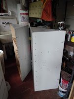
The work is delayed, it has rained a lot to work abroad.
Waf has rebelled and forced to remove my tackle so they have gone to the sink waiting for the weather to improve....
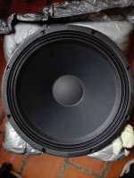
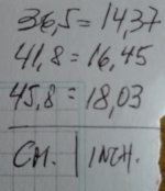
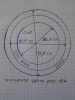
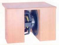
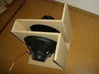
So I have made some measurements in situ of the speaker. These are the actual dimensions, for obvious reasons, I prefer to use 18 inches, equivalent to a speaker overall diameter of 45.8 cm.
The work is delayed, it has rained a lot to work abroad.
Waf has rebelled and forced to remove my tackle so they have gone to the sink waiting for the weather to improve.
So I have made some measurements in situ of the speaker. These are the actual dimensions, for obvious reasons, I prefer to use 18 inches, for the use of the calculator equivalent to a speaker diameter of 45.8 cm.
(I insist that it is created to put that value, and the result will be approximate)
Waf has rebelled
and forced to remove my tackle so they have gone to the sink waiting for the weather to improve....So I have made some measurements in situ of the speaker. These are the actual dimensions, for obvious reasons, I prefer to use 18 inches, equivalent to a speaker overall diameter of 45.8 cm.
The work is delayed, it has rained a lot to work abroad.
Waf has rebelled and forced to remove my tackle so they have gone to the sink waiting for the weather to improve.
So I have made some measurements in situ of the speaker. These are the actual dimensions, for obvious reasons, I prefer to use 18 inches, for the use of the calculator equivalent to a speaker diameter of 45.8 cm.
(I insist that it is created to put that value, and the result will be approximate)
Attachments
Last edited:
I did notice it sky rockets the diagram displacement so It might be better left out.
Hi WaVeInFoRm, this question is unanswered.....
You could explain to me what you mean, please, you have me intrigued !
well. any means to create more sound at lower frequency will result in more cone motion. be it equalizer or compactor, I Know with a smallish box you will need more amp to move the cone as the frequency lowers. I presume but do Not know if the same apples for using a capacitor. somebody else can answer That one...
so it might Not be better left out. if it can somehow allow the cone to move more at lower frequancys with less power that it would take to move the cone more at lower frequancys with a dsp/equaliser and the extra amplifier power. (to level the response)
At a guess, the power from the amp you need to move the cone for a given volume or output level at saaay 30 hz will be the same regardless of if you use dsp or a capacitor to fix and level the responce, as it is caused by physics. the resistance of the vacuum of the chamber the speaker is housed into. that must be over come with more amplification than had you built the boxes abit bigger
the question is... (for the professionals...........)
can you get the driver to xmax in 150l and still be within its power handling?
if so. what is the best way to ammend the responce? so it playes uniformly. is it to boost the lower notes (or diminish the higher range). or is it to use a capacitor to alter the signal response? i dont know enough but I sence the capacitor is sorta working like a equalizing circuit for the woofer to reject more hight frequency information than Lower frequency information. someone should clarify for you,
well. any means to create more sound at lower frequency will result in more cone motion. be it equalizer or compactor, I Know with a smallish box you will need more amp to move the cone as the frequency lowers. I presume but do Not know if the same apples for using a capacitor. somebody else can answer That one...
so it might Not be better left out. if it can somehow allow the cone to move more at lower frequancys with less power that it would take to move the cone more at lower frequancys with a dsp/equaliser and the extra amplifier power. (to level the response)
At a guess, the power from the amp you need to move the cone for a given volume or output level at saaay 30 hz will be the same regardless of if you use dsp or a capacitor to fix and level the responce, as it is caused by physics. the resistance of the vacuum of the chamber the speaker is housed into. that must be over come with more amplification than had you built the boxes abit bigger
the question is... (for the professionals...........)
can you get the driver to xmax in 150l and still be within its power handling?
if so. what is the best way to ammend the responce? so it playes uniformly. is it to boost the lower notes (or diminish the higher range). or is it to use a capacitor to alter the signal response? i dont know enough but I sence the capacitor is sorta working like a equalizing circuit for the woofer to reject more hight frequency information than Lower frequency information. someone should clarify for you,
Thanks, now I understand what you mean. I hope so, (highlighted in bold) although I have not had much luck in this regard, and I tried to make them smile a little but it does not work ... this is a too serious forum!
I have some sims to answer some of your points, then upload them, the limitation in Xmax 6.7 mm seems to be an insurmountable obstacle, but Xlim is 15 mm, and according to my hearing level in my room I do not think it reaches that point. Anyway, I will tell you that if the result is not satisfactory, I will add tuned ports as Eminence suggests for this speaker and solved the problem. I do not think that I need REW, nor DSP, for me it is more than enough the level reached by my system in sound quality, in my particular listening conditions.two 18 inch drivers at 6.7mm at 25 hz is reasonable enough. the thing is getting the driver to play 6.7mm at 25hz and with how much power.
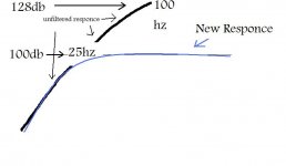
The main thing is to bring down the far louder output in the higher bass (steep responce curve) to = Shallow of flat responce curve.
so if, for say your 100db at 25hz and 110 at 40hz and 125 at 80
you need to find a way to make it... 100db at 25hz 100db at 40hz 100db at 80
of corse it does not haaave to be wholey flaat, a gentle rising responce would be fine.
and there is also room gain to consider,
so for say... if the responce curve is like half a mounting. you need to chop of the top of the mounting so its even at all frequancys. then you will still get a decent enough output across the range with 2 18 inch drivers with 6.7 mm xmax and it sound good too.
what you need to figure, is how much power is needed to get to 6.7mm at (for say) 25hz in 150liters, and is it within the drivers power handleing capability. should be ok at a guess. but the resonance curve Is steep and I do recommend some active equalization to solve that and make it a good subwoofer set.
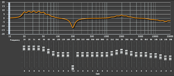
Quick example picture portraying what I mean,
not saying 100db is the max could be 110 or such. This is just to illustrate
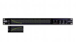
one lazy way would be to wack a 21band eq inline before the amp and then use that sorta in reverse to the speakers curve, at that range of the frequancy responce. should do the trick
(u just turn down aaal the freq above 100hz then you rise each one abit more in a curve untill at 20hz its +12db where as 100hz is at -12db and use that before the crossover in the amp and the amp itself. I hope I am explaining that last bit well enougth. you can get the types they use in rack mounts easy enougth and they have plenty of bands to play with, all you need to do is reshape the responce curve. so for say it was like this
20hz 40hz 80hz 120hz
u turn 125hz and all above to about -12
then 80hz would be -6
40hz +6
20hz +12
about that...... but thats the bassic idea portrayed anyway.
The main thing is to bring down the far louder output in the higher bass (steep responce curve) to = Shallow of flat responce curve.
so if, for say your 100db at 25hz and 110 at 40hz and 125 at 80
you need to find a way to make it... 100db at 25hz 100db at 40hz 100db at 80
of corse it does not haaave to be wholey flaat, a gentle rising responce would be fine.
and there is also room gain to consider,
so for say... if the responce curve is like half a mounting. you need to chop of the top of the mounting so its even at all frequancys. then you will still get a decent enough output across the range with 2 18 inch drivers with 6.7 mm xmax and it sound good too.
what you need to figure, is how much power is needed to get to 6.7mm at (for say) 25hz in 150liters, and is it within the drivers power handleing capability. should be ok at a guess. but the resonance curve Is steep and I do recommend some active equalization to solve that and make it a good subwoofer set.
Quick example picture portraying what I mean,
not saying 100db is the max could be 110 or such. This is just to illustrate
one lazy way would be to wack a 21band eq inline before the amp and then use that sorta in reverse to the speakers curve, at that range of the frequancy responce. should do the trick
(u just turn down aaal the freq above 100hz then you rise each one abit more in a curve untill at 20hz its +12db where as 100hz is at -12db and use that before the crossover in the amp and the amp itself. I hope I am explaining that last bit well enougth. you can get the types they use in rack mounts easy enougth and they have plenty of bands to play with, all you need to do is reshape the responce curve. so for say it was like this
20hz 40hz 80hz 120hz
u turn 125hz and all above to about -12
then 80hz would be -6
40hz +6
20hz +12
about that...... but thats the bassic idea portrayed anyway.
Attachments
Last edited:
31 band then..
see, you bassically set the eq as a inverse flipped version of the response curve and that will levelize it.
if thats enouth eq... im not sure. 24db! Is a fair amount. should be. may not even need Thaat much in which case you alter it accordingly.
then wack the eq infront of the amp. and still use in inamp crossover and it should be fine.
Attachments
This would also provide you with the option of when listening louder to boost the lower frequency's less and turn up the higher ones somewhat and have more usable output for say 40hz - 100hz
to me 25hz is practical to work with or 30 as you will still get some output to 20 but if u leveled it all flat to 20 I sence you lose tooo much spl. but a eq would provide you room to play so where you opting for a flat responce or rising slope you Can do that. the output of the system will be volume limited by displacement at chosen cut off
the sim for your driver/box if its 96db at 20, 100db at 25hz it is 113db at 100hz
so working with 25hz, on the equalizer you would simply turn 100hz down 13db on the equalizer etc I tired now. screen fatigue
I hope my example helps. in actuality you dont need to equalize it Thaat much. But Using a equalizer I would Highly recommend for this design of yours.
Last edited:
two 18 inch drivers at 6.7mm at 25 hz is reasonable enough. the thing is getting the driver to play 6.7mm at 25hz and with how much power.
The main thing is to bring down the far louder output in the higher bass (steep responce curve) to = Shallow of flat responce curve.
so if, for say your 100db at 25hz and 110 at 40hz and 125 at 80
you need to find a way to make it... 100db at 25hz 100db at 40hz 100db at 80
of corse it does not haaave to be wholey flaat, a gentle rising responce would be fine.
and there is also room gain to consider,
so for say... if the responce curve is like half a mounting. you need to chop of the top of the mounting so its even at all frequancys. then you will still get a decent enough output across the range with 2 18 inch drivers with 6.7 mm xmax and it sound good too.
what you need to figure, is how much power is needed to get to 6.7mm at (for say) 25hz in 150liters, and is it within the drivers power handleing capability. should be ok at a guess. but the resonance curve Is steep and I do recommend some active equalization to solve that and make it a good subwoofer set.
Quick example picture portraying what I mean,
not saying 100db is the max could be 110 or such. This is just to illustrate
one lazy way would be to wack a 21band eq inline before the amp and then use that sorta in reverse to the speakers curve, at that range of the frequancy responce. should do the trick
(u just turn down aaal the freq above 100hz then you rise each one abit more in a curve untill at 20hz its +12db where as 100hz is at -12db and use that before the crossover in the amp and the amp itself. I hope I am explaining that last bit well enougth. you can get the types they use in rack mounts easy enougth and they have plenty of bands to play with, all you need to do is reshape the responce curve. so for say it was like this
20hz 40hz 80hz 120hz
u turn 125hz and all above to about -12
then 80hz would be -6
40hz +6
20hz +12
about that...... but thats the bassic idea portrayed anyway.
Well, I have enough to study your observations, thanks for that.
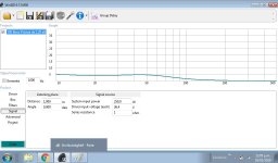
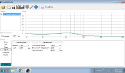
In my post 25 onwards there are the simulations that I have obtained with WinIsd, there are some that I do not understand, for example the Cone excursion is just a straight line at the 6.7 mm point, something must be wrong there ..
Attachments

This would also provide you with the option of when listening louder to boost the lower frequency's less and turn up the higher ones somewhat and have more usable output for say 40hz - 100hz
to me 25hz is practical to work with or 30 as you will still get some output to 20 but if u leveled it all flat to 20 I sence you lose tooo much spl. but a eq would provide you room to play so where you opting for a flat responce or rising slope you Can do that. the output of the system will be volume limited by displacement at chosen cut off
the sim for your driver/box if its 96db at 20, 100db at 25hz it is 113db at 100hz
so working with 25hz, on the equalizer you would simply turn 100hz down 13db on the equalizer etc I tired now. screen fatigue
I hope my example helps. in actuality you dont need to equalize it Thaat much. But Using a equalizer I would Highly recommend for this design of yours.
Thanks again, when I hear the final result, I'll see if I need a professional equalizer, instead of the simple cut-off frequency selector on the board amplifier
:RE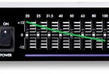
In my post 25 onwards there are the simulations that I have obtained with WinIsd, there are some that I do not understand, for example the Cone excursion is just a straight line at the 6.7 mm point, something must be wrong there ..
The red line shows xmax. There should be another line that shows actual excursion at power specified.
Sometimes if the driver specs are not inputted in the correct way (see winisd help file) then you will not get a plot for xmax.
A pic for example of how it should look :
edit: your graph does show xmax along the bottom. Increase the signal power to bring it up you are probably viewing at 1w.
Attachments
Last edited:
Hello,
I think you should not buy an equalizer, this will never give you the desired result, as long as you don´t have an ampifier with serious output. Serious would be 300w/8ohms in your case.
See, this driver is made for large displacement boxes. You can decrease the volume, but the low end will suffer. This is because the movement of the cone is restricted by the volume of air in the box. To overcome the restriction, you have to increase the power input at low frequency. This is done by some form of equalizing, if done in a physical correct way, you end up with a "Linkwitz Transformation". Theoretically you can go as low as you want with as little volume you want. There is only one "BUT". You have to put huge amounts of power into the speaker. Typical, low frequency/low volume Linkwitz Subs are happyly using 1000 Watts in a normal listening room. This would be more than enough power for a concert in a music club, but with "normal" size loudspeaker cabinets.
Besides from finding the right correction curve for your speaker, you need a large amplifier. If you feed 10 watts to the speaker at 80 Hz and want to keep the 40 Hz linear with a 12 dB correction, you need 100 Watts. So the power demand is x10! With power compression and high x-max this increases even more.
Please try to understand this. Today a 1000 W amplifier is not expensive, but now there comes the next double problem: The speaker can only handle a limited power level and the excursion of the cone is limited.
thats physics, as sad as it sounds.
If you think of a vented box as a miracle solution, sorry. The vented box needs even more volume and with small housings the vent becomes very long to give a boost at low frequency. This is no way for your construction.
The condenser in line with the speaker enables the speaker to take more power from the amplifier.
If fitted right, at a point where the impedance curve of the speaker in the cabinet rises to high resistance (resonance frequency), making the amplifier virtually "weaker", it reduces this effect.
This can NOT be done in the same way by some kind of equalizing before the power amps output!
The concept is too often misunderstood. Simulations give a good idea of the effect, but the final, "best" value of the condenser (around 1000 micro F usually) will best be tried out by measuring the output of the finished sub woofer. In my experience your are usualy +-200microF off with the simulation.
As you only have to find out the best low frequency response and do only plots to compare, you can use any cheap microphone and some free ware measuring software.
So the usual excuse "I don´t have a measuring microphone" does not count.
High capacity audio condensors are expensive. But there is a perfect way to get around this: Take two of for example 50V 2200uF electrolytic´s and connect them + side to + side. So you have a bipolar 1100uF condenser, good for audio. For peace of mind put some "good" audio condensors in parallel, for fine tuning. I usually use 90% electrolytic and 10% of the capacity in film condensors.
Last edited:
Maybe you should think of using these speakers in a dipol / ripol configuration. No box and the construction is not much larger that the two speakers diameter. But, again, you need some serious power.
Look here:
Neighbor friendly dipole sub
Look here:
Neighbor friendly dipole sub
Attachments
Last edited:
Well, I have enough to study your observations, thanks for that.
In my post 25 onwards there are the simulations that I have obtained with WinIsd, there are some that I do not understand, for example the Cone excursion is just a straight line at the 6.7 mm point, something must be wrong there ..
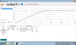
Just to expand a little on Rob Wells' comments, the upper red line on your picture is a reference marker added by WinISD to let you easily see/remember what Xmax is for each driver modelled.
The lower red line is the actual excursion of your project.
You need to increase the applied voltage (Signal tab>"Driver input voltage (each)") until the 2 lines cross at whatever you think the lowest frequency your program material contains, then check the SPL graph.
I'd disagree with WaVeInFoRm about using a graphic EQ as your tool to correct the LF rolloff in a project like this.
Although the physical layout of the device makes it look like you can adjust each band of frequencies individually, in reality the filters are often not anywhere near precise enough to add together smoothly when you make similar adjustments to adjacent bands. This leads to uneven results when used as suggested. Examples here: Boulder Sound Guy - Miscellaneous Frequency Response Curves #1 here: Graphic Content | The Small Venue Survivalist and here:
A Parametric EQ, or a dedicated Linkwitz Transform circuit, or anything like a MiniDSP that can let you build your own filters will let you get more precise results than a graphic IMO.
Well, I have to admit and thank you that all of you have put many technical contributions that I understand and appreciate. Although they do not understand my limitations, which are much more complicated than they suppose. Here the controllers that I would have used are not available, so I was about to buy JBL 1541 D and it escaped me. Now, I have this controller and I will have to extract the maximum potential that is possible in low frequencies with it.
Once again, remember, just add the second octave, to the first I know that I will not get or interest me.
I will be a little more extensive in future responses, individually to each one of you, but for now let me start with wave in form ...
You're right, it was by default at 1 watt, so I changed it to 250 watts and you can see the result here.
"Cone excursion" is now approaching Xlim speaker (15 mm) ....
Eminence says:
XMAX/XLIM
Short for Maximum Linear Excursion. Speaker output becomes non-linear when the voice coil begins to leave the magnetic gap. Although suspensions can create non-linearity in output, the point at which the number of turns in the gap (see BL) begins to decrease is when distortion starts to increase. Eminence has historically been very conservative with this measurement and indicated only the voice coil overhang (Xmax: Voice coil height minus top plate thickness, divided by 2). The Xmax figures on this website are expressed as the greater of the result of the formula above or the excursion point of the woofer where THD reahes 10%. This method results in a more real world expression of the usable excursion limit for the transducer. Xlim is expressed by Eminence as the lowest of four potential failure condition measurements: spider crashing on top plate; Voice coil bottoming on back plate; Voice coil coming out of gap above core; or the physical limitation of cone. A transducer exceeding the Xlim is certain to fail from one of these conditions. High pass filters, limiters, and enclosure modeling software programs are valuable tools in protecting your woofers from mechanical failure.
Understanding Loudspeaker Data | Eminence Speaker
Well, my comfortable listening level (and something else too) in my room will never reach Xlim ...
I have observed that a box says "resistance series", by default it is 1 ohm. I will use 2 x 8 in parallel, should I put 4 ohms?
Thanks for clarifying the point !
Attachments
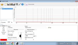
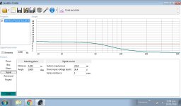
I have observed that a box says "resistance series", by default it is 1 ohm. I will use 2 x 8 in parallel, should I put 4 ohms?
Thanks for clarifying the point !
That box is for any extra series resistance between the output of the amplifier and the speaker's terminals - in a multiway box for example, a passive crossover can add extra series resistance.
For a sub, that shouldn't be the case, so one or two tenths of an ohm to account for the speaker cables themselves is all you should need to have here.
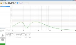
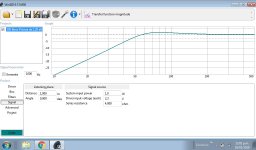
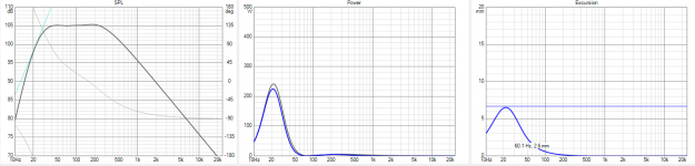
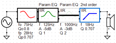
Quickly done in VituixCAD with active blocks & SPL set for Xmax. 80L sealed box in half-space, so you should have significant boundary/room gain with corner cabinets.
The straight line in the SPL chart shows Xmax-limited output versus frequency. And you can see the Linkwitz Transform's enormous power increase in the bottom octave. Adjust LF extension to suit.
The straight line in the SPL chart shows Xmax-limited output versus frequency. And you can see the Linkwitz Transform's enormous power increase in the bottom octave. Adjust LF extension to suit.
Attachments
- Status
- This old topic is closed. If you want to reopen this topic, contact a moderator using the "Report Post" button.
- Home
- Loudspeakers
- Subwoofers
- Eminence Delta Pro 18 A in prism sealed 150 liters