How does one measure the volts of it? Is it by looking at the change in the impedance curve and calculating the difference in volts from that?
Hi shredhead,
The most direct way is to measure the diaphragm displacement.
Back EMF = Bl * u volts
Where Bl is the driver magnetic flux density x voice coil conductor length in telsa.m and u is the voice coil velocity in metres per second
Assuming a rigid driver diaphragm:
u = 2 * Pi * f * Dd / (1000 * Sqrt(2))
Where Dd is the mean-to-peak diaphragm displacement in mm at a given frequency f in hertz
Therefore:
Back EMF = Bl * 2 * Pi * f * Dd / (1000 * Sqrt(2))
Numerical example:
If Bl = 15 T.m and Dd = 0.5 mm at 100 Hz then
Back EMF at 100 Hz = 15 * 2 * Pi * 100 * 0.5 / (1000 * Sqrt(2)) = 3.33 volts rms
Kind regards,
David
Nice, pedantic BS.
In Post #12 you stated that "Back EMF is just motional impedance". This is simply not correct. If correcting your error makes me a pedant, then so be it.
Next you'll tell us that back EMF is -BL*u and that is ever so helpful to the original poster...")
If you read my Post #42, you will find in fact that it is the key to answering his/her question.
Series connection actually increases the damping factor.
The speaker wire contributes most to the damping factor, and if you use the same wire for either parallell or series connection you will have more current trough the cable in parallell setup and also much higher voltage loss.. When it comes to dipole sub woofer speakers you can add a resistor in series 1-2 ohms to get that deep fluffy sound.
Actually most people like that sound when you do a demo.
Specially if you have an elementwit low Qts <0,4 (not suited for dipole) You can add a resistor and get the Qts to 0,7

Insulting posts deleted and points issued. Remember that some members are trying to learn, and that all technical levels are to be catered for with courtesy and respect.
Crap I missed it. If it was aimed at me there is no need for censorship. No one here is going to hurt my feelings. This site is pretty tame compared to what I'm used to.
@sreten -If you could find the link to that or any data about that, it would be awesome!
@David -thank you for the formula.
I plan on doing some more experiments at the end of the week, I'll post more stuff then and await more insults...
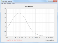
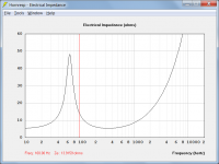
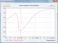
Back EMF and motional impedance are two sides of the same coin
Back EMF is measured in volts and varies with Eg.
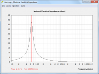
Motional electrical impedance is measured in ohms and is independent of Eg.
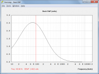
The attached charts show the theoretical Back EMF (at Eg = 2.83 volts) and motional electrical impedance, for an Eighteen Sound 10W400 driver mounted in an infinite baffle.
The obverse and reverse sides of the coin look pretty different to me.
So your pedantry is wasted, and you forgot a minus sign....
You will find that "Back EMF" is positive by definition. The negative sign is only required if "Back" is omitted, as in EMF = -10 volts.
I forgot nothing.
Attachments
Crap I missed it. If it was aimed at me there is no need for censorship.
It was not. Those who received points know who it was aimed at.
Back EMF is measured in volts and varies with Eg. Motional electrical impedance is measured in ohms and is independent of Eg.
The attached charts show the theoretical Back EMF (at Eg = 2.83 volts) and motional electrical impedance, for an Eighteen Sound 10W400 driver mounted in an infinite baffle.
It is precisely because Back EMF is proportional to input that motional impedance doesn't change with input. I can run sims in "software I wrote" that prove my point as well, but I'll spare you. Believe me David, I know what you have produced and you don't have to get ridiculously puffed up about a perceived slight.
Motional impedance is the result of Back EMF. True that motional impedance is not an EMF, but anyone but a pedant can forgive a little sloppy language when dealing with hobbyists.
Subtract the back EMF from the input voltage, then calculate current. Calculate impedance that would cause that current given the input voltage - Hey what do you know, you have calculated the motional impedance knowing nothing but the Back EMF and the input voltage! They are not independent, and again, are two sides of the same damn coin no matter how different you think the heads and tails sides look..
The original poster wanted to know how to measure back EMF. Your response was to measure displacement. This is laughable when that is very difficult to measure and all you have to measure is terminal impedance to understand back EMF. I outlined a procedure that showed how to use simple measurements to see how back emf affects power sharing in a series string near the resonance frequency, where its effects are the highest.
The original poster also asked about my comment regarding resonance and impedance changing with input. This is a nonlinear effect that is caused by the suspension being softer for large excursions than it is for small ones. Thermal effects are also something that isn't accounted for in standard models. Basically, T/S parameters are a pretty fair approximation to the system, but there is a lot going on that varies either with frequency or amplitude in a loudspeaker. Cms, BL, Rms, even "mass" (lumped in from the acoustic side) and inductance changes with excursion and/or frequency.
The question remains if there is some sort of non-linearity or acoustic loading effect that can cause series connected drivers to get out of sorts. For that question I don't know the answer, but it isn't out of the realm of possibility. IF I were making a Car SPL system with multiple expensive drivers, I'd probably drive them either in parallel or each with its own amplifier. Nowadays amplification is often cheaper than the drivers.
Last edited:
I can run sims in "software I wrote" that prove my point as well,
Excellent, I would be very interested to see them.
True that motional impedance is not an EMF,
Motional electrical impedance = Back EMF / Voice-coil current
Your response was to measure displacement.
If you read my post, you will notice that I was careful to say that it was the most direct way, not the easiest way. The reason I chose displacement was so that I could readily show how it related to the Back EMF = -Bl * u formula provided by you in Post #23, but which you felt would be of little use to the original poster. I omitted the negative sign for the reason given in my Post #47. To include the negative sign would result in a negative value for motional electrical impedance, which would not be correct.
I look forward to seeing simulations run in software written by you, proving your original assertion that "Back EMF is just motional impedance".
Originally Posted by Ron E
I can run sims in "software I wrote" that prove my point as well,
Yep, i'd like to see them too. Plus can you give us a link to your software, & what is it etc ?
The original poster wanted to know how to measure back EMF. Your response was to measure displacement. This is laughable when that is very difficult to measure and all you have to measure is terminal impedance to understand back EMF. I outlined a procedure that showed how to use simple measurements to see how back emf affects power sharing in a series string near the resonance frequency, where its effects are the highest.
But you didn't provide an answer to the question asked - how to measure the actual Back EMF voltage value. Perhaps you might like to tell us now.
And while you are about it, include a worked numerical example as I did, so that we are left in no doubt as to the process to be used.
Subtract the back EMF from the input voltage, then calculate current. Calculate impedance that would cause that current given the input voltage - Hey what do you know, you have calculated the motional impedance knowing nothing but the Back EMF and the input voltage!
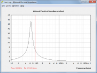
The result calculated using the above method is not even close. For the example checked:
Correct motional electrical impedance = 12.1122 ohms
Result calculated using the above method = 107.3608 ohms
Attachments
How does one measure the volts of it? Is it by looking at the change in the impedance curve and calculating the difference in volts from that?
Hi shredhead,
As pointed out in Post #49, the diaphragm displacement method requires specialised equipment to obtain accurate results, with either an accelerometer or a laser normally being used.
Also as pointed out in Post #47, Back EMF can alternatively be determined by measuring electrical impedance. The advantage of the impedance approach is that less specialised test equipment is required. Unfortunately the calculations become more onerous.
The impedance method requires the following inputs, at a given frequency:
1. Rms voltage applied to the driver voice coil.
2. Magnitude and phase of the normal electrical input impedance of the loudspeaker.
3. Magnitude and phase of the electrical impedance of the voice coil in the absence of motion, that is, when blocked.
Given:
f = Test frequency
Evc = Voltage applied to voice coil
Zen = Normal electrical impedance
Zed = Blocked electrical impedance
Zem = Motional electrical impedance
BEMF = Back EMF in rms volts
Then:
Zem = Zen - Zed
BEMF = Evc * Zem / Zen
If the Re and Le values provided by the driver manufacturer are accurate, it is not necessary to measure the blocked electrical impedance.
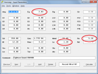
Numerical example using Eighteen Sound 10W400 driver mounted in an infinite baffle:
Measurement frequency = 100 hertz
Measured Evc at 100 hz = 2.83 volts rms
Measured normal electrical impedance magnitude at 100 hz = 13.9159 ohms
Measured normal electrical impedance phase at 100 hz = -50.7642 degrees
Assuming the Re and Le driver specs are accurate:
Re = 5.10 ohms
Le = 1.20 millihenrys
Number crunching with phase angle converted to radians:
Ren = 13.9159 * Cos(-50.7642 / 180 * Pi)
Xen = 13.9159 * Sin(-50.7642 / 180 * Pi)
Red = 5.10
Xed = 2 * Pi * 100 * 1.20 / 1000
Rem = Ren - Red
Xem = Xen - Xed
R1 = (Rem * Ren + Xem * Xen) / (Ren ^ 2 + Xen ^ 2)
X1 = (Xem * Ren - Rem * Xen) / (Ren ^ 2 + Xen ^ 2)
BEMF = 2.83 * Sqrt(R1 ^ 2 + X1 ^ 2)
BEMF = 2.4632 volts rms
You can now see why I chose the diaphragm displacement method originally, for my example
.Kind regards,
David
Attachments
But if I can offer anything as a mechanical engineer, there is no such thing as being too pedantic. Either your explanation is accurate and complete, or is isn't.
Hi zettairyouiki,
As a mechanical engineer you certainly know the consequences of lack of attention to detail. It's exactly the same for an electrical engineer.
As far as I am concerned, it's just part of trying to be professional and in everything that you do - and that includes being respectful to others.
Kind regards,
David
Haha, my apologies David. You're quicker than I am. I contemplated and deleted the reply because I wasn't sure the rest of the reply really added much to the discussion before I saw that you had already quoted me.
Hi zettairyouiki,
Not a problem
.As you would have seen from my response, I thought you raised a very valid point, particularly having regard to what transpired earlier.
At this stage I think I have just about bludgeoned Back EMF / motional electrical impedance to death. Even a devout pedant runs out of steam eventually!
It certainly looks like Ron has had enough
.I really would have liked to have seen his software, though...
Kind regards,
David
JBL don't mention 3dB.Here is an attached snippet from JBL about it. ..................
Wouldn't it be 3dB difference unless you doubled the power to the drivers as well as going parallel?
in para4 they correctly state the power delivered by a bridged amp into 4ohms is "exactly" the same as delivered into 2+2ohms (stereo). That's 0dB.
The back emf of coupled drivers will be substantially the same, because they are coupled by the air load in front of them.............It is for reproducing ULF with sealed sub systems. This means I am pushing the limits of the drivers for certain soundtracks with content at 10Hz and below.
I am starting to think that your method of measuring the impedance curve of the different connection schemes is the only way to measure anything about back EMF. The only other way I can think of to do this would involve manually moving the cone of a driver and measuring the peak effects but I don't see that being very consistent or accurate.
Last edited:
- Status
- This old topic is closed. If you want to reopen this topic, contact a moderator using the "Report Post" button.
- Home
- Loudspeakers
- Subwoofers
- Back EMF Theory...