Can someone help me by devising a test that I can do to measure back EMF with multiple subs with dual voice coils hooked up in different configurations?
back EMF is a lower level detail of the dynamic speaker voice coil motor modeling
the useful electrical description that already takes into account the back EMF is the electrical terminal apparent impedance
all you need is the Theil Small and XO model or just direct electrical impedance measurement
people just confuse themselves trying to bring EMF into the description of amp-speaker interaction
I am trying to measure the difference in wiring subs parallel/series vs. series/parallel. There are a few driver manufacturers who recommend against wiring the drivers in series and I would like to test what the difference is.
I understand I will have to test many frequencies in the sub bandwidth to compare the 2. I'm guessing to test current at different sine wave frequencies since the issue is with amp impedance?
I understand I will have to test many frequencies in the sub bandwidth to compare the 2. I'm guessing to test current at different sine wave frequencies since the issue is with amp impedance?
As jcx said, the back EMF is embedded in the impedance. It tends to cause the terminal impedance to RISE and is correlated to cone/VC motion. The motion generates a voltage which opposes the change which produced it. Pepole tend to think back EMF makes things harder on the amplifier, but that is not the case. Speakers whose motors have a lot of back EMF have input impedances which are more sensitive to cab alignment - small amounts of mechanical damping will have large effects. They are also harder to measure accurately with a typical woofer tester because every little change skews the result.
In general, sepakers with identical impedance curves can be put in series. Ones without should not, because they will interact in ways you probably don't want them to. If the speakers share the same environmet (common chamber) and have nearly identical T/S parameters you are ok. If they vary a lot from unit to unit, or the boxes aren't the same, or are so sensitive to alignmnet that baffle or port placement affects their impedance curves, then a seres connection is ill advised.
In general, sepakers with identical impedance curves can be put in series. Ones without should not, because they will interact in ways you probably don't want them to. If the speakers share the same environmet (common chamber) and have nearly identical T/S parameters you are ok. If they vary a lot from unit to unit, or the boxes aren't the same, or are so sensitive to alignmnet that baffle or port placement affects their impedance curves, then a seres connection is ill advised.
Most likely they advise against series wiring because the subs will not share power equally around resonance due to the impedance curves not being identical.
Cool, that all makes sense. What I'd like to do is take 4 15inch sub drivers of the same make and test the difference between them in different wiring schemes so I can have a practical example of what will happen if you go series.
The things to measure are voltage at the driver's terminals and the current between each driver and do it at different frequencies around the resonant frequency of the driver's, right? Am I missing something to measure to record for this test?
The things to measure are voltage at the driver's terminals and the current between each driver and do it at different frequencies around the resonant frequency of the driver's, right? Am I missing something to measure to record for this test?
Take note, Back-EMF is not a theory, it is a quantifiable, testable, peer reviewed fact.
___________________________________________________Rick.........
___________________________________________________Rick.........
Cool, that all makes sense.
So a couple different people tell you that 2+2=4 and you wish to test it? Here is my suggestion. Study ohm's law and play with different connection types. Once you actually understand ohm's law you will understand how to test it.
Shredhead,The things to measure are voltage at the driver's terminals and the current between each driver and do it at different frequencies around the resonant frequency of the driver's, right? Am I missing something to measure to record for this test?
Yes, simply measure the frequency response and output level using band limited pink noise just under amplifier clipping or current limiting to see which wiring scheme works best for your particular speaker loads. Try it again with the type of music you intend to play, especially if it is music of very low dynamic range that will put a heavy duty cycle on the amps and speakers.
Having measured a variety of cabinets (subwoofers and full range two-way) both series, parallel and series parallel, I found they had the same frequency response regardless of wiring. Frankly, I don't care about back-emf, other than when a load is too reactive for a particular amp to handle, and testing with the particular amp is the way to determine if it is a problem.
As mentioned in previous posts, don't mix different cabinet or speaker types in series, but that would apply to parallel too.
Have fun testing!
Art
Look, I don't mean to pi$$ anyone off. I understand ohms law and I certainly wasn't implying that EMF doesn't exist. I'm just curious about how much power variations can happen at what frequencies with my drivers and how wiring schemes affect this.
Great plan Welter, I didn't think of using noise and comparing it to source material, thanks!
Great plan Welter, I didn't think of using noise and comparing it to source material, thanks!
You might want to check out this post:I'm just curious about how much power variations can happen at what frequencies with my drivers and how wiring schemes affect this.
Great plan Welter, I didn't think of using noise and comparing it to source material, thanks!
http://www.diyaudio.com/forums/subwoofers/204472-multiple-cabinet-combined-response.html
As another point of interest, back in the late 1980's Harry Witz of dB Sound found on long cable runs (many of the tall arenas required over 100' cable runs for flown arrays) the increased damping factor of running their EV MTL4 quad 18" in series parallel (8 ohm), rather than parallel (2 ohm), more than offset the lesser power output, the subs "sounded" louder and punchier even though the speakers were receiving less power.
Art
Last edited:
Back EMF is just motional impedance. This is the impedance peak at resonance. To measure, you just measure impedance curve. If you have a dual voice coil woofer the usual recommendation is for parallel wiring mainly because you get a 6dB gain in output for the same voltage input. Which manufacturers are recommending against series wiring and in what application?
Since you are using DVC woofers, and apparently multiples, it makes me think Car audio or dB drag type application. You don't give enough info about your application, though, to give a good answer to your question. If you aren't pounding the crap out of the woofers, how you connect them will make little difference. If you are pushing the limits, it could make a difference.
Take (for example) 4 woofers (all will have slightly different impedance curves) and put them in series. Either put them in a box (or just set them all on a table or the floor) and measure the total impedance curve. Find the maximum impedance frequency, drive them with that frequency and measure across each set of terminals in turn. Since they all have the same current flowing through them, the voltage across each set of speaker terminals divided by the amplifier voltage represents the "power" dissipated in each. Ideally the voltage across each woofer would be the same - 1/4 the total.
If one woofer measures higher (or lower) than 1/4 the total voltage, that woofer is "getting" more (or less) power at that frequency. Also note, the impedance curve and resonant frequency changes a fair amount depending on input power.
Also note, the impedance curve and resonant frequency changes a fair amount depending on input power.
You lost me here. Why is that, thermal compression or something like that?
Originally Posted by weltersys
EV MTL4 quad 18" in series parallel (8 ohm), rather than parallel (2 ohm), more than offset the lesser power output, the subs "sounded" louder and punchier even though the speakers were receiving less power.
I think that "might" be due to the amps not being able to provide enough sustained current into 2 Ohms ! I know from experience that for eg, Crown 5000's didn't like multiple 18" drivers connected into 2 Ohms per channel. The ODEP lights didn't even come on either, for them to sound rough & unnatural.
@ shredhead
Even before thermal compression takes place, enough heat can be created to increase coil resistance. This alters some of the T/S specs, which therefore changes the response etc !
I think that "might" be due to the amps not being able to provide enough sustained current into 2 Ohms ! I know from experience that for eg, Crown 5000's didn't like multiple 18" drivers connected into 2 Ohms per channel. The ODEP lights didn't even come on either, for them to sound rough & unnatural.
Whether it be the protection circuit kicking in or premature clipping caused by a weak power supply and/or AC line, the speakers were receiving less actual watts when wired for 2 ohms. Even if the amp is supposed to be putting out more, the speakers weren't getting it. Thre Crown VZ amps automatically switch the power supplies from series to parallel, resulting in way less than the spec 5kW at 2R (around 2k-ish). Now drop the AC to 100 volts, and 3/4 of an ohm of speaker cable and connectors, and I'm surprised anything comes out at the end of the hose.
Even before thermal compression takes place, enough heat can be created to increase coil resistance. This alters some of the T/S specs, which therefore changes the response etc !
The increase in resistance IS the thermal compression. Other shifts in the T/S may occur before the coil heats up - and certainly will after. Back EMF will change the apparent impedance, even if the "resistance" of the coil itself does not change. Some heat is being generated long before the output drops enough for anyone to notice, but technically that is still thermal compression. Even if it's only 1/2 a dB.
EMF (back or otherwise) is electromotive force measured in volts.
How does one measure the volts of it? Is it by looking at the change in the impedance curve and calculating the difference in volts from that?
at the speaker terminals it is only a detail linking voice coil motion to electrical side, exactly as useless as thinking about a transformer circuit model by dropping down to flux linkage, induced emf
the driver just looks like an electrical impedance at the terminals
the driver just looks like an electrical impedance at the terminals
If you have a dual voice coil woofer the usual recommendation is for parallel wiring mainly because you get a 6dB gain in output for the same voltage input. Which manufacturers are recommending against series wiring and in what application?
Since you are using DVC woofers, and apparently multiples, it makes me think Car audio or dB drag type application. You don't give enough info about your application, though, to give a good answer to your question. If you aren't pounding the crap out of the woofers, how you connect them will make little difference. If you are pushing the limits, it could make a difference.
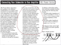
Here is an attached snippet from JBL about it. Stereo Integrity and JL audio both make the same recommendation. I have heard this recommendation from many sources over the years.
Wouldn't it be 3dB difference unless you doubled the power to the drivers as well as going parallel?
My application is not car dB drag racing. It is for reproducing ULF with sealed sub systems. This means I am pushing the limits of the drivers for certain soundtracks with content at 10Hz and below.
I am starting to think that your method of measuring the impedance curve of the different connection schemes is the only way to measure anything about back EMF. The only other way I can think of to do this would involve manually moving the cone of a driver and measuring the peak effects but I don't see that being very consistent or accurate.
Attachments
- Status
- Not open for further replies.
- Home
- Loudspeakers
- Subwoofers
- Back EMF Theory...