I drew it as red here. If you don't consider the cone volume, S2 goes to zero for an infinite compression ratio. Obviously that's not the case in reality. It seems to be implied that the TH118 is made in that way.
No, S2 is not zero in that picture. Draw it out as a straight horn without any folds or bends and you will see that it's not zero.
If S2 was zero the line would have no cross sectional area at that point. That's clearly not the case.
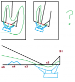
Just for reference I modified your pic to show what it would look like if S2 was actually zero. In this pic S2 is zero and the throat chamber (the cone divot) is the only way for the air to get around the bend. You can see now why I said I can't imagine any situation where S2 would ever be zero.
An externally hosted image should be here but it was not working when we last tested it.
I unfolded it and drew in the horn path to clear confusion. I can't make sense of your drawing since it's a dead end the way I'm reading it.No, S2 is not zero in that picture. Draw it out as a straight horn without any folds or bends and you will see that it's not zero.
The way I drew it S2 is zero. It's only when you add the cone volume that the path makes sense.
Attachments
Ok, I see what you are saying now. I thought the red line in your drawing was an open hole and the driver fired through that hole.
Are you sure that's what is in the TH118 commercial model? I find it very unlikely, as the holes that connect the small triangle at the beginning of the horn to the throat chamber, and connect the throat chamber to the rest of the line, would be TINY. Like maybe 1/5 Sd or something small like that. And if the TH118 and the TH115 are the same box with different size drivers, the TH115 holes would be even smaller.
This picture shows how small the holes would be (in yellow). Those holes would be TINY. Is that really what's in Danley's box? Wouldn't the driver need a spacer ring so the cone didn't smash against the red line in the pic?
An externally hosted image should be here but it was not working when we last tested it.
Never actually seen the internals, though I know some here have, but my best guess is that the area in question is similar to the ss15 v2. When you apply that change to the TH18, you'll also squeeze a bit more path length out. (pictured is somebody's guess on the SS15 v2 dimensions. I don't think jbell ever gave a really complete finished plan for it)I thought XOC1's design was regarded as being almost an exact clone of the commercial TH118. This recent drawing is SIGNIFICANTLY different than XOC's design. Anyone know for sure what's in the commercial TH118?
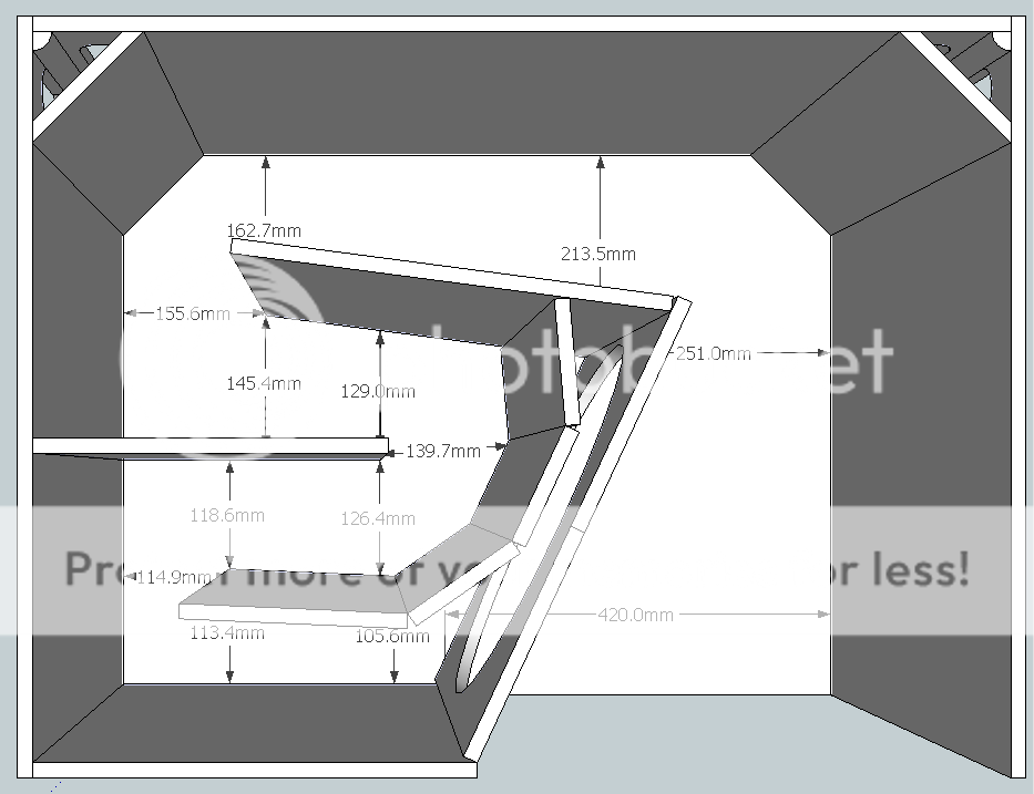
The panel across from the middle of driver (hence s2) may be even closer or simply incorporated into the baffle itself on the TH118. That would give you zero s2.
Zettairyouiki drew a Danley TH118 line drawing - You don't believe him?
The devil is in the detail. There is a baffle between the cone and the rest of the speaker. a speaker is not a line drawing. Still makes S2 zero. Not easy to model that in Hornresp - Just trying to make sense of the fact that without the cone correction method some speakers can not be simmed.
We make very good speakers using hornresp but it is leading us all down a path that is not necessarily the only way to make a decent tapped horn.
I'm not going to post up a TH118 image - Danley made that public knowledge some time ago.
Crescendos results in the TH18 thread are valid, every dB is sacred and hard won!
Attachments
Last edited:
Zettairyouiki drew a Danley TH118 line drawing - You don't believe him?
The devil is in the detail. There is a baffle between the cone and the rest of the speaker. a speaker is not a line drawing. Still makes S2 zero. Not easy to model that in Hornresp - Just trying to make sense of the fact that without the cone correction method some speakers can not be simmed.
We make very good speakers using hornresp but it is leading us all down a path that is not necessarily the only way to make a decent tapped horn.
I'm not going to post up a TH118 image - Danley made that public knowledge some time ago.
After a bit of searching it does appear that Zettairyouiki's drawing may be correct.
I am fairly certain the reason it was done this way was to squeeze in an extra few inches of path length, not for the reasons that "cone correction" is advocated on this forum.
The drawings I found in my search indicate the holes are indeed very small, leading to high compression ratios and this is likely the reason this design shreds cones (or surrounds), so I wouldn't really call this a positive feature.
Crescendos results in the TH18 thread are valid, every dB is sacred and hard won!
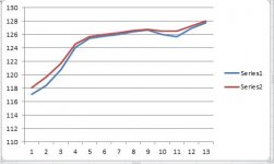
The graph you posted doesn't mean anything. The horizontal axis is labelled 1 - 13, there is no legend explaining what the red and blue lines mean, and there is no information about what is being measured (or simulated - or whatever is going on here). No information about measurement conditions (if this is a measurement), and no way "cone correction" provided that boost in the low end, if that's what this graph is intended to show. Even if "cone correction" was responsible for this boost in the low end (it's not - see Ricci's measurements) it wouldn't matter because the only place there's more than 1/2 db of difference in the low end is clearly below tuning and would be filtered out by the high pass filter.
Last edited:
Hardly. Just trying to demonstrate a concept (zero s2) that can be difficult to visualize without a drawing.Zettairyouiki drew a Danley TH118 line drawing - You don't believe him?
It somewhat seems to me that a few people are attributing a bit of voodoo to "cone correction" that isn't deserved. It's simply acknowledging that the cone does contain a certain volume, quite significant in the case of an 18, that will throw off simulations of the throat of a tapped horn. Correcting for that additional volume may be significant in some designs, and insignificant in others. Dismissing the concept because it's not a big change in one instance doesn't make much sense.
The correction's raison d'être isn't necessarily to control the cone or to raise compression. It merely brings the physical design and the simulation into agreement. Those are certainly possible changes you could find in the performance of the revised design, however.
Again I will admit much ignorance when it comes to the higher level design theory that may be in play in tapped horns, especially when it comes to the mechanics of Danley's designs, but I don't really think there is any "secret sauce" at play here. I imagine it's simply a very well refined design that's required plenty of sawdust to tweak even after you're done with the simulations. Without accounting for cone volume, you won't even be making the most of the simulations.
That's why some people's phobia of engaging in clean room engineering here still somewhat surprises me. Even as a hobby, the pursuit of every "sacred and hard won dB" is a natural consequence. I realize that referring to drawings of the TH118 would violate that principle, and I respect that completely. But we've come to the point where "cone correction" definitely does not qualify as a secret sauce. It's easy to see why a straight panel offset from the baffle isn't necessarily the most ideal way to design a throat.
Anyways, I'm concerned I'm very much off on a tangent here, bring in bits of discussion from other threads. I certainly respect the people who have made the advances we're working with possible. I only wish I had the resources and knowledge to participate seriously. I'm still learning.
Last edited:
Hardly. Just trying to demonstrate a concept (zero s2) that can be difficult to visualize without a drawing.
I found a few images just like this which show your drawing was right on the money. I don't necessarily think this is a good idea, I think it's why this design is famous for shredding cones.

It somewhat seems to me that a few people are attributing a bit of voodoo to "cone correction" that isn't deserved. It's simply acknowledging that the cone does contain a certain volume, quite significant in the case of an 18, that will throw off simulations of the throat of a tapped horn. Correcting for that additional volume may be significant in some designs, and insignificant in others. Dismissing the concept because it's not a big change in one instance doesn't make much sense.
The correction's raison d'être isn't necessarily to control the cone or to raise compression. It merely brings the physical design and the simulation into agreement. Those are certainly possible changes you could find in the performance of the revised design, however.
Simulating a throat chamber will show clearly the effect of the cone divot. Even for a large cone like an 18 inch driver it really doesn't make much difference. This is verified with Ricci's measurements. Hornresp doesn't have enough segments to sim this though, it would need to be done with Akabak.
Last edited:
Simulating a throat chamber will show clearly the effect of the cone divot. Even for a large cone like an 18 inch driver it really doesn't make much difference. This is verified with Ricci's measurements. Hornresp doesn't have enough segments to sim this though, it would need to be done with Akabak.
Right. I don't think VTC in hornresp is really a complete solution, but I understand what you mean. I do think a little philosophy is involved, though. One dB here and a half dB there is from an objective standpoint very little difference. Almost imperceptible. Driver to driver variation is likely to be higher. It's still something that people will be interested in pursuing though.
Absolutely, people should be interested in this (and all aspects of design). Ricci's measurements show that you can tweak the response curve a bit. But only in the higher frequencies and only a little bit. You won't get lower extension and 2 db extra output though, as people on this forum claim.
I don't believe that the mods to the Othorn as outlined in post 44 of this thread were ever going to be effective.
The Othorn already has a high compression ratio. Much higher than most designs ever posted on DiyAudio. Adding even more obviously did not work.
Also I don't agree with the cone shape that he added in the horn path which I consider not ideal at all.
PASC posted a link to Post 744 in the TH18 thread
http://www.diyaudio.com/forums/subwoofers/190635-th-18-flat-35hz-xoc1s-design-75.html#post3146783
In this CRESCENDO reported positive effects from adding more S2 compression to the TH18.
The TH18 does benefit from more compression. It is difficult to simulate this, unless the cone correction curve method is used.
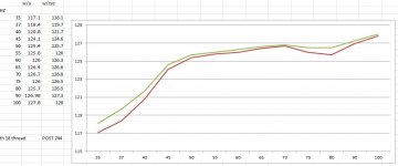
Hornresp can be use to simulate a different shape but it means making the rest of the horn far more inaccurate in order to see the effects in the area of interest.
Screengrab is same data but with Hz axis. Red is without cone correction green is with. Is that clear enough?
The Othorn already has a high compression ratio. Much higher than most designs ever posted on DiyAudio. Adding even more obviously did not work.
Also I don't agree with the cone shape that he added in the horn path which I consider not ideal at all.
PASC posted a link to Post 744 in the TH18 thread
http://www.diyaudio.com/forums/subwoofers/190635-th-18-flat-35hz-xoc1s-design-75.html#post3146783
In this CRESCENDO reported positive effects from adding more S2 compression to the TH18.
The TH18 does benefit from more compression. It is difficult to simulate this, unless the cone correction curve method is used.
Hornresp can be use to simulate a different shape but it means making the rest of the horn far more inaccurate in order to see the effects in the area of interest.
Screengrab is same data but with Hz axis. Red is without cone correction green is with. Is that clear enough?
Attachments
Can someone please give me some cliff notes?
My take: In this thread: http://www.diyaudio.com/forums/subwoofers/178029-c-e-x-pa-flat-30-ft30-pa-th-awesomeness.html seems like crescendo’s (and epa) designs and sims did well to 30hz but nobody built anything and later the overall goal to achieve flat to 30hz was just abandoned and then the xoc1 TH18 was developed and now we’re trying to see if cone correction will make it flat (or closer) to 30hz. In the meantime Ricci developed the OTHORN… Seems to me the 6 fold design or that ugly looking octopus EPA thing should be revisited…
My take: In this thread: http://www.diyaudio.com/forums/subwoofers/178029-c-e-x-pa-flat-30-ft30-pa-th-awesomeness.html seems like crescendo’s (and epa) designs and sims did well to 30hz but nobody built anything and later the overall goal to achieve flat to 30hz was just abandoned and then the xoc1 TH18 was developed and now we’re trying to see if cone correction will make it flat (or closer) to 30hz. In the meantime Ricci developed the OTHORN… Seems to me the 6 fold design or that ugly looking octopus EPA thing
should be revisited…
Last edited:
I don't believe that the mods to the Othorn as outlined in post 44 of this thread were ever going to be effective.
The Othorn already has a high compression ratio. Much higher than most designs ever posted on DiyAudio. Adding even more obviously did not work.
Also I don't agree with the cone shape that he added in the horn path which I consider not ideal at all.
You don't agree with the cone shape?!? You think a small piece of wood near the driver lowers tuning AND excursion, but only if the compression ratio was high to begin with?!?
This is getting ridiculous.
I had some time so I did some sims. I'm not sure why other people don't do this kind of thing too, instead of blindly believing in subjective reviews and questionable measurements that clearly are not correct, or even possible.
This first picture shows Ricci's Othorn measurement from earlier, along with frequency response and excursion sims. In each case the red line is with "cone correction", the darker line is without. This shows EXACTLY what you would expect. The measurement matches the sim. The sim predicted the change due to "cone correction" almost perfectly. And note that there's no change at low frequencies, and no reduction in excursion. This is EXACTLY what you would expect if you look at this from an objective standpoint instead of believing subjective fairy tales and questionable measurements like the one you showed.
An externally hosted image should be here but it was not working when we last tested it.
Now here's another example. This design has a VERY low compression ratio, 1.76:1. I've shown it with (red) and without (dark) a 10 liter throat chamber, which is a VERY large throat chamber for a driver of this size. Again, EXACTLY what you would expect. A huge throat chamber lowers tuning about 1 hz, which is what happens when you add a huge throat chamber. The large chamber LOWERS tuning, if you fill that chamber in, tuning will RISE. And of course the lower the tuning, the higher the excursion. You can see all this clearly in the sim.
I'm sick and tired of people saying that simulations are not useful. Don't be so lazy people, do your homework and correlate sims to measurements and you will see that there's no magic going on. Ever.
An externally hosted image should be here but it was not working when we last tested it.
PASC posted a link to Post 744 in the TH18 thread
http://www.diyaudio.com/forums/subwoofers/190635-th-18-flat-35hz-xoc1s-design-75.html#post3146783
In this CRESCENDO reported positive effects from adding more S2 compression to the TH18.
The TH18 does benefit from more compression. It is difficult to simulate this, unless the cone correction curve method is used.
Hornresp can be use to simulate a different shape but it means making the rest of the horn far more inaccurate in order to see the effects in the area of interest.
Screengrab is same data but with Hz axis. Red is without cone correction green is with. Is that clear enough?
[/QUOTE]Clear enough, but clearly not correct. There's something wrong here. Either in the measurement conditions, driver conditions, or something else. This just isn't how it works. Look at my pictures above, do some sims of your own, and you will see that there's something very wrong here. Even if there wasn't something wrong, the extra db on the low end is completely useless, it's below tuning and will be filtered out by the hpf.
Last edited:
Well, I just let my friend borrow my pair of xoc1 th18 (v1, no cone correction), as he just received a pair of th118 from danley for testing. My cabs are 18 nlw 9601 8 ohm loaded.
I had work today so u was unfortunatly not able to attend.
No measurements were taken, but I immediatly received a txt to tell me that subjectively "the danley are much cleaner" I am unsure if his danley are 4 or 8 ohm cabs
I had work today so u was unfortunatly not able to attend.
No measurements were taken, but I immediatly received a txt to tell me that subjectively "the danley are much cleaner" I am unsure if his danley are 4 or 8 ohm cabs
Last edited:
So You adjusted the size of the chamber but did you adjust the rest of the speaker to keep the same overall volume or did that lower response come from a bigger cabinet?
Have you ever tried to set out a folded cabinet and adjust all the size parameters and get it to fit in the box? It is not that easy!
Have you ever tried to set out a folded cabinet and adjust all the size parameters and get it to fit in the box? It is not that easy!
Yes this is ridiculous, I have not got a clue what you are on about.You don't agree with the cone shape?!? You think a small piece of wood near the driver lowers tuning AND excursion, but only if the compression ratio was high to begin with?!?
This is getting ridiculous.
So You adjusted the size of the chamber but did you adjust the rest of the speaker to keep the same overall volume or did that lower response come from a bigger cabinet?
Have you ever tried to set out a folded cabinet and adjust all the size parameters and get it to fit in the box? It is not that easy!
Why would I adjust the rest of the speaker to keep the volume the same? The volume isn't the same. If you do "cone correction" to an existing design that doesn't already have it (which is the case most of the time here, and it's definitely the case with the othorn example measurement and sim) you are subtracting volume from the cab, volume taken up by wood. In this case the only way to get a lower response is from increasing the throat chamber size. You don't get a lower tuning by filling in the throat chamber, as people as claiming.
Not sure what you are asking. I have folded horns and I have reverse engineered folded horns. I do it properly and with great accuracy with advanced centerline method. It really isn't difficult. It takes a bit of time but it's not hard.
Yes this is ridiculous, I have not got a clue what you are on about.
I was paraphrasing what you said. I've shown proof to back up my claims, you've shown some type of flawed measurement that doesn't make any sense and some odd comments. This is what you said.
I don't believe that the mods to the Othorn as outlined in post 44 of this thread were ever going to be effective.
The Othorn already has a high compression ratio. Much higher than most designs ever posted on DiyAudio. Adding even more obviously did not work.
Also I don't agree with the cone shape that he added in the horn path which I consider not ideal at all.
I'm not sure how anyone could look at the Othorn sim and measurement I showed and say that "cone correction" can't be simulated, or that it has some mystical qualities that give lower extension and better cone control and 2 more db. The sim matches the measurement almost exactly wrt the difference between open throat chamber and "cone corrected".
Last edited:
DSL TH118 are all 4 ohm. For a short period of time 18sound drivers were used (with some problems of cone wobble at certain frequencies, corrected by 18sound in later runs), then they switched to B&C18AW115-4.Well, I just let my friend borrow my pair of xoc1 th18 (v1, no cone correction), as he just received a pair of th118 from danley for testing. My cabs are 18 nlw 9601 8 ohm loaded.
I had work today so u was unfortunatly not able to attend.
No measurements were taken, but I immediatly received a txt to tell me that subjectively "the danley are much cleaner" I am unsure if his danley are 4 or 8 ohm cabs
The "cleanliness" of the DSL may be attributed to the S1 "stub" employed in the DSL TH118 as well as the different drivers.
Art
- Status
- This old topic is closed. If you want to reopen this topic, contact a moderator using the "Report Post" button.
- Home
- Loudspeakers
- Subwoofers
- Othorn vs XOC Th118 comparison for fun.