I agree that having a real life operating unit thanks to Sabaspeed says it all about this non-issue. There is another driver that you guys may want to take a look at: Infinity 1260w for $62 shipping included. It is even higher sensitivity than Alpine and has huge xmax of 13mm Qts of 0.39, 93dB sensitivity, and 300watt rating. I have used it in several other tapped horns designs and the sims are pretty amazing for the price.
http://s3.amazonaws.com/szmanuals/663ab8fc44823217fd87abef74b72ce5
Infinity Reference 1260w 12-Inch 1200-watt High-Performance Subwoofer (Single Voice Coil):Amazon:Car Electronics
If you guys want to take a crack at the design in HR first I will also try in AkAbak.
The FS is pretty low on that one (for these higher FB boxes) but other specs look good ..... I bet it does sim well in a low tuned tapped pipe or similar .... If used on a box with a higher FB (relative to FS) then a good electronic high pass filter with sharp slope would be absolutely required to be safe ..
I agree that having a real life operating unit thanks to Sabaspeed says it all about this non-issue. There is another driver that you guys may want to take a look at: Infinity 1260w for $62 shipping included. It is even higher sensitivity than Alpine and has huge xmax of 13mm Qts of 0.39, 93dB sensitivity, and 300watt rating. I have used it in several other tapped horns designs and the sims are pretty amazing for the price.
http://s3.amazonaws.com/szmanuals/663ab8fc44823217fd87abef74b72ce5
Infinity Reference 1260w 12-Inch 1200-watt High-Performance Subwoofer (Single Voice Coil):Amazon:Car Electronics
If you guys want to take a crack at the design in HR first I will also try in AkAbak.
PS they rate the "sensitivity" as 2.83 V in car. so not really useful for comparing drivers as it takes into account some cabin gain and well 2 watts to the driver.
The FS is pretty low on that one (for these higher FB boxes) but other specs look good ..... I bet it does sim well in a low tuned tapped pipe or similar .... If used on a box with a higher FB (relative to FS) then a good electronic high pass filter with sharp slope would be absolutely required to be safe ..
I like how we both answered this simultaneously
") what Matthew said is basically what I was getting at, didn't have fun trying to tune it to 35 Hz, might work down in the sub 20 range.
what Matthew said is basically what I was getting at, didn't have fun trying to tune it to 35 Hz, might work down in the sub 20 range.I've planned on rounding over (routing the edge) of the internal corner edges.
Thoughts?
I think that is a great idea
I've planned on rounding over (routing the edge) of the internal corner edges.
Thoughts?
He mentioned that using a roundover bit on the port would be minimally useful as the flare radius he was talking about is on the order of inches, like 1.5 ish. Couldn't hurt. I would round over the entire external of the box if I didn't have to go to the shop to do it. I just used an orbit sander.
I like how we both answered this simultaneously
I think that is a great idea
Not sure if he's reffering to the mouth edges or the panels on the interior namely the ports and baffle. IMO can't hurt to try it, especially if you have a decent router, I've only dealt with a router that tends to drop bits at bad times (luckily they mainly get loose rather than completely go flying). At school they have better one's but I minimize my time there because the meter is insanely expensive.
According to model, size of the mouth doesn't affect fb. The fb is dictated by volume before constriction, TL length before constriction, and constriction width and length. Mouth size may affect how well the tapped-pipe 6th order bandpass feedback works and may reduce or extend bandpass so that HF cutoff changes.
Mr XRK ,
Try to think of the two pipe sections as being connected in series with the constriction connecting the two , as far as the fundamental resonance is concerned both segments (and the constriction) add to the total path length of the cabinet .... Opening up the mouth too much actually starts to subtract from the path length, and closing up the mouth area also shifts the FB down by adding mass loading ... The effect isn't extreme, but it is there ....
XRK, I believe you may be correct when you say that mouth area will definitely change the resonant behavior of the small chamber (higher midbass resonance) , the effect on this midbass resonance is likely to be more abrubt than the effect upon FB but still follows the same pattern of shifting upwards with an increased mouth area and shifting downward with a reduced mouth area .... Of course Hornresponse doesn't properly acknowledge the extra midbass resonance that the small chamber (or plenum or whatever we choose to call it) contributes so i can only demonstrate the effect on the box fundamental until i learn how to use Akabak ...
Take a look at the 3 attachments, the shift in FB is slight, but it does occur ....
Keep in mind that the '"magnet in mouth" arrangement (configured as it is sketched) shifts the FB down a little more, so these three examples are actually predicting on the high side, but of course we are "splitting hairs" here .......
We are all such a bunch of hair splitters!
Attachments
It may shift fb a little but the fundamental tuning freq is dictated by the first TL pipe, the constriction is the boundary edge of the quarter wave pipe. If there is anything else downstream is a "new" mode and cannot "add" to the length of the first pipe - not for such a rapid drop in CSA from the TL to the constriction. Then the amount of constriction serves to "mass load" the fb lower. Downstream of the constriction the second pipe or plenum is much too short to have any significant 1/4 wave effect on the bass frequencies. Lengthening it is like making the magnet bigger - adding more "mass loading" due to constriction or pressure losses.
I have been trying it out in multiple softwares and the results show that velocity is well within the safe range ...
Which softwares? I mentioned twice that there is only one program that can show velocity at the restricted area in this design. And I showed two softwares that show you are nowhere near the safe range.
So we have 3 or 4 guys saying this isn't a problem. We have software that says it is a problem. We have no measurements.
We do have one cab built and one guy that says he can't hear audible chuffing, which isn't too surprising since he probably hasn't stuck his head inside the mouth when operating at xmax or beyond. But I would be very surprised if measurements didn't show compression effects at spl levels lower than a simple ported box (with a properly sized port) could do. In Flare It I've turned off allowances for seating distance and masking by content. When turned on those things allow for a whopping 55 percent more velocity. That means the blue chuffing line moves up to 15 m/s at 35 hz. And because the port is buried a foot or so inside the box the chance that you will ever hear identifiable chuffing is probably fairly small unless you stick your head in the mouth. BUT the chances of onset of early port compression and reduced output at high excursion are extremely high.
Flare It is a good little program to let us know when things get too small. And it's a best case scenario since it assumes round ports. We all know (or should know by now) that things get more restrictive with high aspect ratios and in this design the constriction ratio aspect is very high.
Anyway it's not my time and money so I don't care much about this issue but it would be nice to see some high power measurements or at least show how or why my observations with the software are incorrect.
Not sure if he's reffering to the mouth edges or the panels on the interior namely the ports and baffle. IMO can't hurt to try it, especially if you have a decent router, I've only dealt with a router that tends to drop bits at bad times (luckily they mainly get loose rather than completely go flying). At school they have better one's but I minimize my time there because the meter is insanely expensive.
I was planning on rounding over everything but the internal corners (that might be "rounded" via (say, a 45 degree) a corner piece, but can't be rounded over, because it is almost impossible to round over a concave shape).
I really like my DeWalt router.
Last edited:
I like how we both answered this simultaneously
True, I was designing 20Hz tapped pipe or tapped horns with it. Maybe make ML-TransFlex "Grande"?
It may shift fb a little

Do you suppose this could be seen as a good feature of this design? Meaning this gives us some amount of flexibility in the shape and size of mouth/terminus without affecting the FB too much ...
Since it doesn't appear anyone is even going to bother to check velocity at the constriction or answer my questions here's a picture.
36 volts into the script from post 167, filters, diffraction and boundary reflections turned off.
First graph is frequency response, second is excursion, third is velocity at Duct (2) D8.

36 volts into the script from post 167, filters, diffraction and boundary reflections turned off.
First graph is frequency response, second is excursion, third is velocity at Duct (2) D8.
And since no one wants to use the appropriate software, try this as a thought experiment. If you reduced the constriction to 1 sq cm, would that still be ok in your opinion? Hornresp will still report the mouth velocity as being very low. The sim won't show any port compression at all, because software doesn't show port compression.
Several people are arguing that since this is inside the box it doesn't matter but when you have 26 - 30 m/s rushing by a sharp corner you are going to have massive turbulence, there's no way around that. Turbulence equals distortion, that's a fact.
And there's not a whole lot else to say, except that measurements are required.
I was wondering why you say turbulence equals distortion. Do you mean harmonic distortion? Turbulence is simply what happens when flows have eddies and vortices and do not flow in a parallel line flow. The majority of flow inside the speaker is turbulent due to the large length scales which make the Reynolds number > 2300 (the transition from laminar to turbulent). Turbulence in the constrictor duct just adds more resistance and losses. The frequencies it generates will be in the 100's of Hz to kHz, well above the sub 100Hz passband we are trying to use it for. You will hear a sound not unlike the sound a vacuum cleaner makes when you listen to the air flow going into the attachment hose. If this duct is shaded from direct exposure to sound radiation output, such as in this case, it will sound quite attenuated. But it will not add to 2f, 3f, 4f, 5f components of audio signal to the excitation frequency - it will be broadband noise - a signature of turbulence.
Having said all this, I do agree that we should strive to aim for velocities below 20m/s for regular program levels. I think velocity excursion into 30's of m/s are OK for peak levels which are not continuous for the reasons shown above.
I don't agree it will be "massive" turbulence. The characteristic length (L) of the duct is 3.5cm or 0.035m, the kinematic viscosity (nu) of air is about 1.64^-4 m^2/s (at 70 deg F). The velocity at peak is 30m/s. The Re number = U*L/nu=30*0.035/(1.64^-4)=6400. This is really mildly turbulent as high turbulence is in the Re 100,000 and above. I don't think there is that much noise associated with this level of turbulence. Note that this is only at peak excursions. Most music program levels will play about 10dB (3x less) below assuming you leave this for headroom, then it is right at the transition of turbulence at 2130 Re. This matches the observations of Sabaspeed who listened to it and could not hear any chuffing.26 - 30 m/s rushing by a sharp corner you are going to have massive turbulence, there's no way around that.
Having said all this, I do agree that we should strive to aim for velocities below 20m/s for regular program levels. I think velocity excursion into 30's of m/s are OK for peak levels which are not continuous for the reasons shown above.
Last edited:
Since it doesn't appear anyone is even going to bother to check velocity at the constriction or answer my questions here's a picture.
36 volts into the script from post 167, filters, diffraction and boundary reflections turned off.
First graph is frequency response, second is excursion, third is velocity at Duct (2) D8.
An externally hosted image should be here but it was not working when we last tested it.
Thanks for running this for us. Rather than display screenshots, you can go to edit copy as bitmap and paste to a png file for posting. It make nicer graphs if you want to avoid the windows border.
Since it doesn't appear anyone is even going to bother to check velocity at the constriction or answer my questions here's a picture.
Hey JustAguy,
Thank you for the graphs, I am exploring this right now, i am using various forms of software to see what the results are and they are all over the place to say the least .... I am mainly simming the Alpine in 35hz and 40hz boxes which end up being very similar if using the same software ...HR of course says the velocity figure is 10m/s at 38v in the actual ML-TP model, and most of what i am seeing from other software (as reflex) says that we are staying within the safe range, even up to 500 watts, but i do have just one piece of software that ALMOST agrees with your velocity curve (at 25m/s) ... Other softwares are telling me figures such as 7m/s , 6m/s , and another software shows me something even lower than that , suspiciously low actually
...... Needless to say i am now taking all of these figures with a "grain of salt" due to inconsistency..I have another software called Subwoofer Simulator that will let me sim series tuned 6th order bandpass boxes which are a Helholtz equivalent to our ML-Transflex boxes, It will be interesting to see if that velocity result is any higher compared to just using simple reflex sims ..
Anyway, If i was limited to saying one word to describe these software velocity results i think that the word i would use is: "DUBIOUS"
Apparently these softwares use different models to calculate velocity, and they cannot all be correct!

If i were to go with the average it looks like Hornresponse is pretty close so far.....
Last edited:
Matthew Morgan,
The AkAbak velocity is for the constrictor duct. The velocity scales inversely with the CSA so if it is 10m/s in the mouth or main duct and CSA of constrictor is 1/3 (say) of the main duct, then velocity in constrictor duct is 3x higher. There is nothing inconsistent with what HR says and what AkAbak says if you check velocity in AkAbak at the mouth. They will be equal. It is just that in AkAbak one can probe the velocity at any point inside the speaker - including the face of the cone driver.
The AkAbak velocity is for the constrictor duct. The velocity scales inversely with the CSA so if it is 10m/s in the mouth or main duct and CSA of constrictor is 1/3 (say) of the main duct, then velocity in constrictor duct is 3x higher. There is nothing inconsistent with what HR says and what AkAbak says if you check velocity in AkAbak at the mouth. They will be equal. It is just that in AkAbak one can probe the velocity at any point inside the speaker - including the face of the cone driver.
XRK,
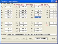
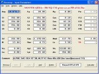
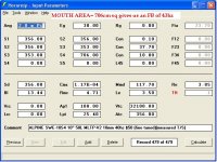
I see, so we really need a measurement at HR's Apt/Lpt section (Maybe we can put in a request with David) , But STILL with that said this doesn't add up since a pipe with an area of 356sq cm shouldn't have a velocity of 10m/s (halfway to the DANGERZONE) at only 38 volts ... If that were the case then all reflex cabinets made for car subs, home subs and whatever else would need MUCH larger ports or they would be blatantly chuffing far too much to be acceptable as they use 2" , 2.5" and 3" diameter ports or high aspect ratio slot vents with equivalent areas and we know about the power levels and xmax ratings involved in some of those apps ...... Yet , no noticeable chuffing takes place in those boxes, even when the ends of the ports are not concealed behind a bandpass cutoff
I see, so we really need a measurement at HR's Apt/Lpt section (Maybe we can put in a request with David) , But STILL with that said this doesn't add up since a pipe with an area of 356sq cm shouldn't have a velocity of 10m/s (halfway to the DANGERZONE
) at only 38 volts ... If that were the case then all reflex cabinets made for car subs, home subs and whatever else would need MUCH larger ports or they would be blatantly chuffing far too much to be acceptable as they use 2" , 2.5" and 3" diameter ports or high aspect ratio slot vents with equivalent areas and we know about the power levels and xmax ratings involved in some of those apps ...... Yet , no noticeable chuffing takes place in those boxes, even when the ends of the ports are not concealed behind a bandpass cutoff - Status
- This old topic is closed. If you want to reopen this topic, contact a moderator using the "Report Post" button.
- Home
- Loudspeakers
- Subwoofers
- New sub design? Constricted Transflex, simple build (series tuned 6th order)