Well, I added some stuffing to the closed end of the line and tried to deal with possible leaks around the driver's frame and damn, it's sounding a lot better now. The damping seems to have dealt with a lot of the harmonic resonances I was hearing and the midbass integration with the main speaker (I was using one of the Blastomaras for testing purposes) is so much better that the combination sounds like one big speaker, even though there's only a simple 12dB/octave filter @ 100 Hz on the TL.
The measured impedance curve reflects these changes. The blips in the curve above 70 Hz have almost completely disappeared, and the lower impedance peak has moved down in frequency a bit. I still have a bit more work to do on this particular build, but I'm lot happier with it now. Ultimately it's proven that (1) the TL2 configuration works as predicted and (2) the Advanced Centerline Method for calculating path length works very well (in this case it was off by 0.5%(!))

The measured impedance curve reflects these changes. The blips in the curve above 70 Hz have almost completely disappeared, and the lower impedance peak has moved down in frequency a bit. I still have a bit more work to do on this particular build, but I'm lot happier with it now. Ultimately it's proven that (1) the TL2 configuration works as predicted and (2) the Advanced Centerline Method for calculating path length works very well (in this case it was off by 0.5%(!))
Hi Brian,
thanks for the update. great results.
I wonder if it's possible to measure the weight of the stuffing you added to give us an indication of how much is required to get great results like this please?
I'd suspect other 1/4 resonators will get similar benefit, perhaps?
Cheers.
thanks for the update. great results.
I wonder if it's possible to measure the weight of the stuffing you added to give us an indication of how much is required to get great results like this please?
I'd suspect other 1/4 resonators will get similar benefit, perhaps?
Cheers.
I don't think I have anything that could accurately measure the weight of the stuffing I used, but I estimate it was between one to two pillows' worth. Basically just about enough to fill up the section before the first bend. And yes, other 1/4 wave resonators should benefit from similar damping as well. Without the damping, this particular 1/4 wave resonator build had a response that was a bit too coloured for me to consider it acceptable for the purpose I had in mind.
Time to start on the write-up for my website...
Time to start on the write-up for my website...
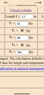
This I what you should build (use 270 cm) instead of all that ‘140 dB SPL/30hz’ pipe dreaming 😝Pillows!!! yeah !!!!
8/2.54, (rumored as the Egyptian version of pi)! Also a very good approximation of end correction for a 3 meter pipe(3.1496062992….)😝. The creepy weird sequence of doubling in the decimals of results of (/2.54) in numbers, etc
8/2.54 x 360 can be use for the speed of sound as can pi x 360 and pi^2 works as gravity on earth as well…
this is all encoded in the 432 harmonic and ‘3’. The 3/4,9,15,21,27…. Resonances in qw pipes etc..
random nonsense unless you add end correction and reality to the ’perfect’ math midels it produces(insert Martin King or Horn response or whatever needed additional math regarding actual speaker ducts?)
Attachments
Last edited:
😱😝
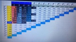
The number system extends to all the harmonics (/3) and allows you to ‘see’ how great full range TLs are created too, by driver offset@ 0.3333(ignoring end correction and boundary) …. It’s super intersting!
whats so cool About the metric system is that meters and qw freqs are the same in reverse ….
270 cm is 32 hz
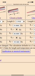
320 cm is 27 hz
this collides if/when you use 345.6 m/sec as speed of sound
(345 is x^2 basis for pythago (2d) and 3456 is just the x^3 version
all harmoincs are then based on 3(chart) and …
if we note the speed of light is ~3.0 x 10^8 meters and (432)^2 is 186624(~speed of light in miles and….
the reciprocal of the driver offset (0.349) is 1.864 +1. And the remaining qw pipe length is exactly 1.864 as a fraction
😝can of worms for geek nerds to rabbit hole into more of this and once you use it, you discover siubd/electric/magnet…. resonance…. It’s all the same (almost) and …numerology finds fact.
The number system extends to all the harmonics (/3) and allows you to ‘see’ how great full range TLs are created too, by driver offset@ 0.3333(ignoring end correction and boundary) …. It’s super intersting!
whats so cool About the metric system is that meters and qw freqs are the same in reverse ….
270 cm is 32 hz
320 cm is 27 hz
this collides if/when you use 345.6 m/sec as speed of sound
(345 is x^2 basis for pythago (2d) and 3456 is just the x^3 version
all harmoincs are then based on 3(chart) and …
if we note the speed of light is ~3.0 x 10^8 meters and (432)^2 is 186624(~speed of light in miles and….
the reciprocal of the driver offset (0.349) is 1.864 +1. And the remaining qw pipe length is exactly 1.864 as a fraction
😝can of worms for geek nerds to rabbit hole into more of this and once you use it, you discover siubd/electric/magnet…. resonance…. It’s all the same (almost) and …numerology finds fact.
Attachments
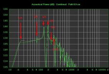
That impedance curve suggests that a driver with very different parameters than those defined in Hornresp was used for the build. The impedance peaks are also at different frequencies compared to the build, suggesting that the build doesn't match the sim. The heights of the impedance dips suggest that the build is lossy, and finally, the upmost impedance peak is degraded, suggesting that the box is not properly braced.
See http://www.diysubwoofers.org/projects/other/impresp/
See http://www.diysubwoofers.org/projects/other/impresp/
Hi,
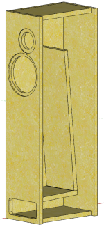
even if this thread is dedicated to folded horns I've seen in one of the 51 (!) pages a picture of a folded TL (like the one I'm designing).
Perhaps somewhere there are also the measures allowing me to understand what happens in a folded line of a TL.
Does anybody have any of these measurements?
Thanks
Attachments
- Home
- Loudspeakers
- Subwoofers
- Spreadsheet for Folded Horn Layouts...