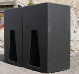
TL with a compression throat chamber could also be a rear loaded horn or "scoop."
Some RLH's can be modeled as a TH or BP6S.
Some RLH's can be modeled as a TH or BP6S.
Dude!? Look at that screw mechanism to adjust the panel🤓
for some reason now everytime i click export its opening up a window like ur computer would if you were saving a file i dont get it
Yup, the newer versions of the spreadsheets will pop up that window if the current save location is invalid. It provides you with the opportunity to set a new location to save the export file.
I was wondering if there is an easy way to interpret the angles made by the sheet? Thank you.
Use the "Guides" feature in the workbook to mark the guides out on the side panels. No need to work out the angles.
When using the type o boxplan, why is it that when loaded into hornresp the size of s2 goes to a crazy high number. thats when you have it in manual. If you click it and change it to auto, it changes to the same number as s1 or s3 etc. this also obviously changes the frequency response dramaticly. Should s2 be matching the size of s1? from my understanding it should with the given style of box. but then again im not sure what is being considered s2 and so on.
Post a picture of your BOXPLAN. Maybe there's a bug in the workbook that needs to be addressed.
Ah, I suspect I know what it might be. Cone compensation. The model that BOXPLAN creates tries to emulate the impact of the volume of air in front of the driver's cone (and the cutout in the panel right in front of it) on the sim. Try putting an "o" instead of an "x" for the "Include Cone Compensation" option. That will turn the option off and S2 should be then equal to S1.
i did do that but it didnt change the problem. I justclick auto insteasd of manual and i would assume thats basically doing the same thing. Or is that not fully showing me an accuarate reslut? also question on changing the x and o, if i remove a panel and then export the boxplan with that panel removed. when i say removed i mean changing the x to an o. Is that just removing the panel in the picture or is that going to be removing the panel all together? basically if i remove the panel in boxplan then important it into hornresp are the results i get going to be the same with the panel removed in box plan that it would be if it was there?
Adding or removing the panels in the spreadsheet is only for identifying which panels are being referred to, when you're trying to figure out cutsheets and their locations. It won't change the corresponding Hornresp sim. Deselecting the cone compensation however WILL change the Hornresp sim.
e.g. these are the Hornresp sim parameters for a sample type O with cone compensation off...

And there are the Hornresp sim parameters for the same box with the cone compensation on, nothing else changed. Note the change to S2.

The increase @s2 is an attempt to approximate the effects of the volume of air in front of the driver's cone that sits between it and the chamber that it faces into.
e.g. these are the Hornresp sim parameters for a sample type O with cone compensation off...
And there are the Hornresp sim parameters for the same box with the cone compensation on, nothing else changed. Note the change to S2.
The increase @s2 is an attempt to approximate the effects of the volume of air in front of the driver's cone that sits between it and the chamber that it faces into.
Attachments
Feature request:
Hello, Brian. I request tapped horn design (especially SFTH style designs) spreadsheets allow for Art Welter style slot, at the horn exit, as an enable/disable feature. As long as exit velocity is within reasonable value, it can improve bass response, low pass filtering and directivity (to some extent).
Regards,
Giri
Attachments
Hi Brian. Wow, this tool is incredibly helpful! I'm currently trying to correct the sim for the THAM15 I've built and posted about over on the relevant thread. This is no doubt a very dumb question but in order to make the last panel of the horn path 90 degrees to the front panel (like the original THAM15), i have changed Expansion 2 to 1.7. This changes the marks corresponding to that panel on the "guides" tab both 29.4 cm so it looks like I was successful but I'm not sure if I've used the correct approach? Thanks for developing these resources!

Last edited:
- Home
- Loudspeakers
- Subwoofers
- Spreadsheet for Folded Horn Layouts...

