looks like that was answered here:Well I trying to build super scoops but want to build them the drivers I am about to purchase. And I thought that was a generic formula for rear loaded horns.
https://www.diyaudio.com/community/threads/pull-apart-a-speaker-design.343408/#post-5952397
which links to this thread: https://forum.speakerplans.com/database-simulation_topic16974_post167079.html#167079
"SuperScooper 21"
s1=804
s2=4092
exp=236
vrc=0
lrc=0
fr=0
tal=0
atc=3093
vtc=74220
Measure taken from http://www.speakerplans.com/index.php?id=21superscooper"

Perhaps they tried to approximate an exponential expansion with a series of parabolic expansions. Hornresp allows a RLH sim to have four sections, but only one section was used in the sim to describe the SuperScooper 21 which, IMO is not an "optimized" design. For example, net volume is a significant determinate of efficiency at low frequencies, so if you find that sections in the box enclosing the horn are being blocked off so they don't horn's volume, then the result is efficiency at low frequencies that's lower than what you can achieve from a box with the same external dimensions. Compare the layout of that SuperScooper 21 to that say of the TH118, were basically almost every cubic cm enclosed by the box's walls forms part of the horn.
Like I said, it can be approximated. Basically approximate one exponential section with multiple parabolic sections that follow the same expansion profile.
I actually offer that option in one or two of my BOXPLAN spreadsheets, where the layout of the horn allows this to be done.
From the drawing for the SuperScooper 21, it looks like that's what they tried to do with its layout, which would explain the blocked off section in the upper part of the horn.
But ideally if the horn can be sim'd using up to four parabolic sections instead, than that's what should be done in Hornresp, as the sim would be more
accurate.
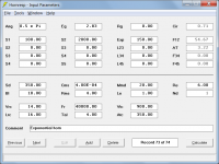
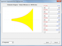
For the frequencies and dimensions involved, there will be no practical difference in performance if the exponential horn is approximated by four parabolic segments.I can't see how that enclosure could match the performance of a TRU exponential rear loaded horn.
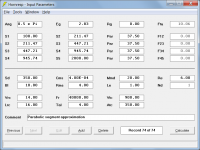
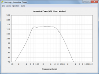
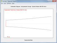
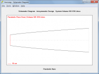
To illustrate, Attachment 1 shows the input parameters for a test single-segment exponential horn. Attachment 2 shows the input parameters for the same horn approximated using four equal-length parabolic segments. Attachment 3 compares the responses of the two horns. The difference is barely discernible.
Attachments
You just build them. There is nothing to adjust.Ok so my question is how can I configure these plans to a particular driver
Use a recommended driver.
For the frequencies and dimensions involved, there will be no practical difference in performance if the exponential horn is approximated by four parabolic segments.
To illustrate, Attachment 1 shows the input parameters for a test single-segment exponential horn. Attachment 2 shows the input parameters for the same horn approximated using four equal-length parabolic segments. Attachment 3 compares the responses of the two horns. The difference is barely discernible.
If that's the case, then why have the PAR, CON, and EXP options at all? Have HR default to EXP for all segments and functions. That would be at least 4 fields we would not have to deal with.
If that's the case, then why have the PAR, CON, and EXP options at all? Have HR default to EXP for all segments and functions. That would be at least 4 fields we would not have to deal with.
You will notice in Post #889 that I said: "for the frequencies and dimensions involved". At low flare rates and frequencies the difference between a true exponential flare and four-segment parabolic approximation is not great (as shown in Attachment 1). At higher flare rates the difference becomes more noticeable (as shown in Attachment 2) and may affect the performance.
I would have thought that it is a lot easier to simulate a true conical or parabolic horn using a single Con or Par segment rather than trying to accurately approximate the profile using multiple Exp segments
.Attachments
In which case you would simulate it using an Exp flare, not a Par flare.THIS is a TRU exponential rear loaded horn.
Now I'm confused - who is saying that?I can't believe you guys are saying that this
Would perform the same if it were built like this
You agreed with Brian Steele that the pic below can be modeled as an exponential rear loaded horn with 4 segments.
I'm saying it should not be. It is a parabolic rear loaded horn and should be modeled as such whether you use 1 segment or 4 segments.
Model what you build, not what some favorable graph spits out from using the incorrect horn profile.

I'm saying it should not be. It is a parabolic rear loaded horn and should be modeled as such whether you use 1 segment or 4 segments.
Model what you build, not what some favorable graph spits out from using the incorrect horn profile.
Sigh, we seem to be going in circles with this.
Someone else modeled this an exponential horn. I haven't delved into the details of whether or not that MODEL is accurate (nor would I, because IMO this horn is not optimized so not with the effort).
What I suggested is that you can approximate an exponential horn expansion with parabolic segments, like David showed in his example. So yes, it is possible to achieve an exponential horn expansion that way in a rectangular box, and the "gap" in the upper right part of this horn's cross-section suggests to me that's what the builder was trying to do, e.g. the horn expansion to the right of that gap is greater than the horn expansion to the left of it, and the horn expansion at the bottom and end of the horn seems to be increasing as well. Whether or not the designer ended up with a true exponential expansion that was approximated by parabolic segments, I don't know.
You agreed with Brian Steele that the pic below can be modeled as an exponential rear loaded horn with 4 segments.
Correct.
I'm saying it should not be.
Then you would be wrong.
It is a parabolic rear loaded horn and should be modeled as such whether you use 1 segment or 4 segments.
It is an exponential horn made up of multiple parabolic segments.
The bottom line is that no one in their right mind would design a bass horn having an overall parabolic expansion rate. The acoustical impedance characteristics would be entirely unsuitable. The system in question was designed by Rog Mogale. There is no way in the world that he would have used a parabolic profile. You can do a simple sanity check for yourself:
The horn system parameters are:
S1 = 60 * 13.4 = 804 cm^2
S2 = 60 * 68.2 = 4092 cm^2
L12 = 236 cm
If the overall or average flare profile of the horn is exponential, then the cross-sectional area half-way along the horn will be 1854 cm^2, making the dimension at that point equal to 1854 / 60 or 30.9 cm.
If the overall or average flare profile of the horn is parabolic, then the cross-sectional area half-way along the horn will be 2466 cm^2, making the dimension at that point equal to 2466 / 60 or 41.1 cm.
The given drawing shows that the actual dimension at the mid point is much closer to 31 cm than it is to 41 cm, meaning that the target profile the designer was aiming to achieve was most certainly exponential (or possibly hyperbolic-exponential), but definitely not parabolic.
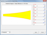
That is exactly what Brian and I are doing, using four parabolic segments to approximate the overall exponential profile of the horn, which is how the system is actually constructed. It is theoretically the most accurate way to do it. However, because the flare rate is relatively low you can get away with modelling the horn using a single exponential segment without introducing a significant error. What you should ideally not do though, is to simulate the system using a single parabolic segment - the difference in horn volume is just too great, as shown in the attachments.Model what you build, not what some favorable graph spits out from using the incorrect horn profile.
Attachments
- Home
- Loudspeakers
- Subwoofers
- Spreadsheet for Folded Horn Layouts...