Depends on where you '**** an ear'")
Thanks GM, I have been "listening" in the wrong places, it would seem
.Unless there is specific information which compares HornResp sim vs measurement which might be interesting for David and others.
I for one, would certainly be very interested indeed in seeing any such comparisons.
I have been wondering for a while now if anyone is actually using the Hornresp paraflex models - the silence has been deafening
WE are alive and using your new PH-models nearly everyday

I picked up some of those models and added some 2D-construction-plans to understand how we use your new Paraflex-Implementation for Hornresp. (Thanks again!
 )
)My target was to get the most accurate simulations for our Paraflex-designs. That means it is possible that some values are a bit "off" because i did the simulations reverse-engineered, based on our or my own measurements (perfect conditions in free field).
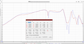
So i did the measurements of the C2E-18 Golden Formular and the PFX 212 Top OLD version (which i also modified with halfmoon-phaseplugs and rear-path restrictions to get it more flat, which was a HUGE success so far and we are still optimizing). Will show the sims and plans in another posting then.
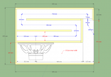
I also optimized the folded Resonator of the C2E GF118 (made it longer and added damping material) to get the wanted flatness in the upper bandwidth and no unwanted ringing - which i already posted (either in this thread or in another one, can't remember).
In the plan i drawed some overlap areas because Hornresp needs solid walls for a "resonator" and we dont have them in reality, but the values are chosen always as a "middled-value" of the relating path-section.
So this is just "a few" simulations of manys.
The PH1 model is the most accurate so far. (for me)
The PH3 model is always a bit off, but still good. (more accurate in models without throat-chamber - TH-like)
Tom Armitage Giles did some inversions of those models, but we lost some fine-tuning of the LF-path and the merge with that technique.
So all in all we did not disappear
WE ARE WORKING!! Speakers are my hobby and in my fulltime-job as a train-driver with work in the early mornings, days, at night, it's sometimes hard to keep up with all the forum-stuff etc. I hope you understand.
If you guys have any further questions or whatever, contact us
Greetz Patrick
Attachments
-
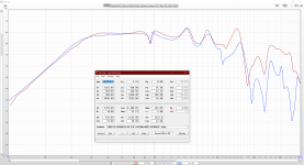 00_C2E_GF_118_Measurement_40cm_HTres_4Caps_PH1_SIM.png292.7 KB · Views: 338
 -
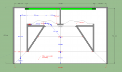 000_PFX212_2D_Plan_OLD.png44.8 KB · Views: 253
 -
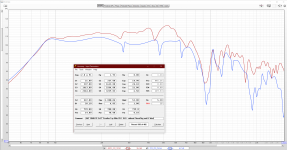 000_PFX212_PH1-Model_VS_Measurement_OLD.png279.5 KB · Views: 235
 -
 Paraflex A-Type 115 118 with 15SW100 2D.png83.3 KB · Views: 239
 -
 Paraflex A-Type 115 with 15SW100 Simu vs Measurement Jay Michaels.png258.9 KB · Views: 305
 -
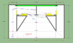
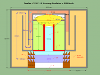 00_C2E_GF_118_18DS115_Hornresp_Simulation_EXPLAINED_2D.png75.3 KB · Views: 309
 -
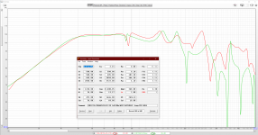
 00_C2E_GF_118_Measurement_40cm_HTres_NoCaps_VS_PH_Sim_001.png264.6 KB · Views: 302
 -
 00_C2E_GF_118_Measurement_40cm_HTres_4Caps_PH3_model.png283.5 KB · Views: 415
Hi grindstone,
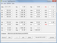
Also, just to check - you have set Ap (the port mouth area) to 200 sq cm and Apt (the port throat area) to 1200 sq cm. Did you mean to specify a negative exponential flare port, or should the figures perhaps be the other way around?
David
Somehow I knew you'd catch that...right when I caught it. In my defense, it was my first one
It's just an interesting thing, this sort of prehensile 4-5 segment. Truly it's the star of this little act of the show. I need to spend more time looking at it and I haven't yet modeled it every which way let alone built or measured anything yet.
THANKS AGAIN!!!!!
PS Really like that single-key filling "switch"!
Last edited:
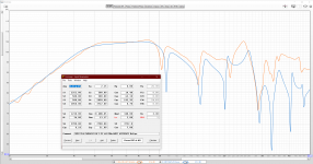
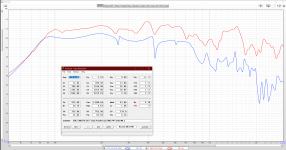
Okay guys, here is the most advanced PFX 212 simulation in PH1 model versus reallife measurement.
S1 and S2 are veeeery sensitive in this case, so i call them the magic data
But nevertheless, the model is pretty accurate although values are a bit off etc.
The best thing is its reallife-sound! Truely on point and "lush" as a builder described them recently! Give it a try
S1 and S2 are veeeery sensitive in this case, so i call them the magic data
But nevertheless, the model is pretty accurate although values are a bit off etc.
The best thing is its reallife-sound! Truely on point and "lush" as a builder described them recently! Give it a try
Attachments


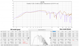
Here is the TC2E-121 ph1 sim VS real measurement taken by Mark Tomlin.
The comparison looks pretty reasonable to me! Thanks Patrick and USRFobiwan, for the great feedback. It seems that the paraflex simulation models are working as intended, and being put to good use after all
.PS Really like that single-key filling "switch"!
You can thank diyAudio forum member 'Mallickarjuna' for that - it was his suggestion
.


And here is te Paraflex Type-R-121 outside 2v measurement vs HornRespo PH1 mode (in blue).
Given the complexity of the paraflex system, I am pleasantly surprised that the predictions are as accurate as they appear to be, for the examples you have provided. Thanks again for the feedback!
The comparison looks pretty reasonable to me! Thanks Patrick and USRFobiwan, for the great feedback. It seems that the paraflex simulation models are working as intended, and being put to good use after all
Yes, quite impressive!

Given the complexity of the paraflex system, I am pleasantly surprised that the predictions are as accurate as they appear to be, for the examples you have provided. Thanks again for the feedback!
Nice work, all. It's almost like this McBean guy knows what he is doing or something...
It's almost like this McBean guy knows what he is doing or something...
Not always...
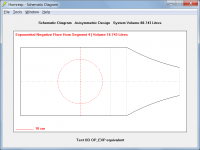
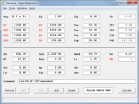
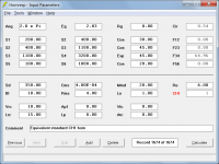
.Just to check that the new ODOFP (offset driver, offset flared port) model is working correctly I set L45 = 0.10 cm and QL = Lossless in your example, and compared the results to those of the almost-equivalent standard offset driver system shown in Attachments 1 and 2. The results are effectively identical with just slight variations in the ripples at the higher frequencies as shown in Attachment 3, which is reassuring.
Attachments
Doesn't look like we can make a bad one if we try ...
Thanks, David. Still swimming in the permutations and wonder of this new sandbox and still just giddy. THANK YOU!!!
Sometimes I make stuff now that, even looking at the system models and both schems, I'm not sure what it is (just kidding).
Oh--one point of business: In the CH1 with the flared port in the LS Wizard, was the Mouth velocity (port velocity or CH velocity) omitted on purpose? No need for gymnastics to add, but if it's there already and it's for free, I'd take the output.
Thanks, David. Still swimming in the permutations and wonder of this new sandbox and still just giddy. THANK YOU!!!
Sometimes I make stuff now that, even looking at the system models and both schems, I'm not sure what it is
(just kidding).Oh--one point of business: In the CH1 with the flared port in the LS Wizard, was the Mouth velocity (port velocity or CH velocity) omitted on purpose? No need for gymnastics to add, but if it's there already and it's for free, I'd take the output.
Last edited:
Maybe one more thing same config: If we could change the path in the LS wizard under chamber with the power displayed sorta "like usual" that would save going out and back in but--again--not if gymnastics are required. That's it--now I'm shutting-up Did I mention THANK YOU!!! ?
Did I mention THANK YOU!!! ?
Last edited:
Doesn't look like we can make a bad one if we try ...
It sure seems that way at the moment
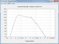
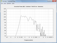
. I have now also "sanity-checked" the OHOFP (offset horn, offset flared port) model. Attachments 1 and 2 show the inputs used, with Attachment 3 comparing the two power responses. There are no discernible differences between the two sets of results, which is great.In the CH1 with the flared port in the LS Wizard, was the Mouth velocity (port velocity or CH velocity) omitted on purpose?
Not on purpose - just one more thing I overlooked
. The flared port outlet peak particle velocity option will be added to the Loudspeaker Wizard in the next update. As is the case currently, the particle velocity at the mouth of horn 2 will still need to be checked from the main screens (after a bit of tidying up is done there to take into account the new offset flare model - yet another thing overlooked).Attachments
If we could change the path in the LS wizard under chamber with the power displayed sorta "like usual" that would save going out and back in
Can't you already do that? It seems to be working okay for me.
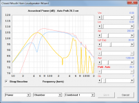
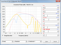
With the Power chart displayed and the Chamber, and Combined or Combined 1, options selected, double-click on the Path Auto label to switch to Path Manual.
Attachments
- Home
- Loudspeakers
- Subwoofers
- Hornresp