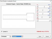
I can't see anything radically wrong with your specified design, assuming that your input values accurately reflect the desired system. Not that it makes any material difference to the results, but I would set S1, S2, S3, L12 and L23 equal to zero, as they serve no real purpose in this case. Hornresp shows the peak velocity. Is WinISD perhaps showing the rms value?
changing those made zero difference, and considering it happened with many drivers, incorrect inputs is probably out the question, so it probably is winisd using rms value. but now my question would be how do I interpret that 80m/s as "good"? I want to design more complex boxes that can only be done in hornresp in the future but I have no idea how large to make ports etc with those much higher values i'm seeing
Even with a port 2x the surface area of the driver i'm still getting these very sharp peaks with what would be considered too high of a port velocity, when obviously my port is more than overkill. I don't see other people getting these sharp peeks, and i'm 100% my entered t/s parameters are correct.
I essentially cannot build a ported box with a sufficient port according to hornresp, which seems very odd
I essentially cannot build a ported box with a sufficient port according to hornresp, which seems very odd
Attachments
I essentially cannot build a ported box with a sufficient port according to hornresp, which seems very odd
I am pretty certain that the Hornresp figures are correct
") . Just to reassure you, I have compared the Hornresp results against those produced by Dr Bjørn Kolbrek's own personal simulation software. Believe me, Dr Kolbrek really knows what he is doing when it comes comes to loudspeaker modelling .
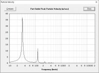
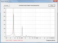
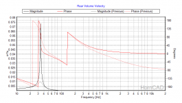
. Just to reassure you, I have compared the Hornresp results against those produced by Dr Bjørn Kolbrek's own personal simulation software. Believe me, Dr Kolbrek really knows what he is doing when it comes comes to loudspeaker modelling .In the example given, Hornresp calculates a maximum peak particle velocity of 30.3 m/sec (see Attachment 1), and Dr Kolbrek's program calculates a maximum rms volume velocity of 0.857 m^3/sec for the same system (see Attachment 2).
Converting rms volume velocity to peak particle velocity:
Peak particle velocity = rms volume velocity * sqrt(2) / cross-sectional area
Port tube cross-sectional area = 400 cm^2 = 0.04 m^2
Therefore peak particle velocity = 0.857 * sqrt(2) / 0.04 = 30.3 m/sec
Which is exactly the same as the Hornresp result, to one decimal place.
Attachments
Even with a port 2x the surface area of the driver i'm still getting these very sharp peaks with what would be considered too high of a port velocity, when obviously my port is more than overkill. I don't see other people getting these sharp peeks, and i'm 100% my entered t/s parameters are correct.
I essentially cannot build a ported box with a sufficient port according to hornresp, which seems very odd
This is why the 'Fates' invented transmission [pipe] lines, horn shaped vents, which BTW can be designed quite accurately in HR.
GM
I am pretty certain that the Hornresp figures are correct
Just to clarify - for a lossless system, that is...
One should keep in mind that Hornresp and similar programs are a small signal simulators, even though a few large signal parameters are included and allow some rough estimation of max SPL etc. Nonlinear suspension, air nonlinearity, inductance modulation, port flow and turbulence etc. are not included. So be careful when tuning designs at high levels.
Port behaviour is well researched so it should be possible to figure out how to do it.
But looking closer into the reason for the narrow peak: I guess WinISD uses a simple lumped model of the enclosure (it looks like it from the single port velocity peak), with a QL value representing all enclosure and port losses. Hornresp uses, AFAIK, a lossless enclosure and port, with the only losses being the radiation from the port. My SW includes a QL value if the Helmholtz frequency can be determined from the equivalent lumped model, which it actually couldn't in this case, as the port was slightly too long for the approximations to hold. Reducing the port length slightly to include QL reduces the port velocity to sensible values. I was surprised by how large impact QL had, so maybe David should include this parameter (can be modelled by a resistor in parallel with Cab) somehow.
maybe David should include this parameter (can be modelled by a resistor in parallel with Cab) somehow.
I will have to think about that idea for a while
.I'm not exactly sure how the feature could be incorporated into Hornresp in a seamless, robust and consistent fashion, and if the value of QL should be specified by the user, or automatically assumed by Hornresp. If the port velocity is particularly sensitive to changes in QL, then the results could become rather arbitrary depending on the value chosen for QL.
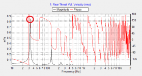
Attached is an example with a QL of 7 (pale lines) and lossless enclosure, both using a lumped parameter model.
The sensitivity will probably depend on port area etc, but the height of the peak seems to be proportional to QL if it isn't to high (approximately double for QL = 7 compared to QL = 3). I think 7 is the standard value used in most SW, and the actual QL must be measured. I'm not sure if people actually would change this value. For this reason it would be possible to use a fixed global QL value that could be turned on and off in the Options page. Or make it available in the Loudspeaker Wizard.
The sensitivity will probably depend on port area etc, but the height of the peak seems to be proportional to QL if it isn't to high (approximately double for QL = 7 compared to QL = 3). I think 7 is the standard value used in most SW, and the actual QL must be measured. I'm not sure if people actually would change this value. For this reason it would be possible to use a fixed global QL value that could be turned on and off in the Options page. Or make it available in the Loudspeaker Wizard.
Attachments
That doesn't necessarily make it unusable. I remember, some 50 years ago, watching my uncle tune ported boxes by pushing a block of wood into the box and fixing it at the length where it sounded right. So if you have the design right, you could tweak it manually in the assembly stage to correct for minor variations in driver parameters and construction.If the port velocity is particularly sensitive to changes in QL, then the results could become rather arbitrary depending on the value chosen for QL.
maybe David should include this parameter.
The QL parameter will be added in the next update.
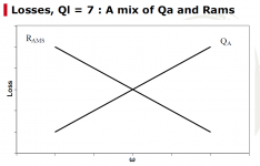
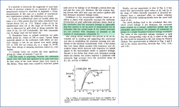
Regarding the QL parameter…this dates back to 1973 and the first Small paper on vented enclosures. The advice given was that losses in a normal vented enclosure may be adequately approximated by a QL~7. But if you read the paper in detail, you will find that Small determined the apparent measured leakage (QL) was not real, but an indication that losses from different sources in the vented enclosure system varied with frequency. More recent papers by Claus Futtrup suggest that using a constant leakage loss in an essentially leak-free enclosure is providing an approximation for the woofer mechanical losses that increase with falling frequency, and enclosure absorption losses that increase with increasing frequency. The attached post-AES convention presentation at the Munich High End Show provides a brief description. There is also a link below to the *.mp3 audio from the actual presentation. A bit more background and detail are included in his chapter on vented enclosures, also attached. His AES paper is the best source, but is not currently available for free download.
Using a QL value in the 5 – 10 range does provide better agreement with measurements of “normal” vented enclosures. But, may(will?) deviate if your system parameters are outside the norm. (ie unusually large enclosure, unusually long port, unusual amounts of damping material or thin enclosure walls...etc). If the option is included in Hornresp, it may be good to add a note, or description in the help file that it provides an approximation of total system losses as recommended by Richard Small for “normal” vented systems. Making QL adjustable in the Wizard between, say, 3 to 20 should cover the range of response for how the vast majority of vented enclosure builds would actually measure.
Links to documents:
Vented-Box-Loudspeaker-Systems--Part-1
http://www.cfuttrup.com/about/15-Scan_Speak.pdf
http://www.cfuttrup.com/about/scan_speak.mp3
http://www.cfuttrup.com/blogspot/Book_05_Futtrup.pdf
AES E-Library >> Losses in Loudspeaker Enclosures
Attachments
Last edited:
Feature Request - Particle velocity display in wizard
Hello David,
One of the last things I check for, in designing a Transmission Line, is the port particle velocity. Based on which I decide the minimum possible TL end cross-section and final taper. Particle velocity is a useful feature to have within the wizard itself. Of course, if it's feasible to do
Thanks for the wonderful work, as always.
Hi bolserst,
Many thanks for posting this information, it is very interesting indeed.
Noted, thanks.
My plan was to include a QL slider having the range 1 to 99, with the default value being 7. Moving the slider control to the very end (just past 99) would select the current lossless model instead.
Kind regards,
David
Regarding the QL parameter…
Many thanks for posting this information, it is very interesting indeed.
If the option is included in Hornresp, it may be good to add a note, or description in the help file that it provides an approximation of total system losses as recommended by Richard Small for “normal” vented systems.
Noted, thanks.
Making QL adjustable in the Wizard between, say, 3 to 20 should cover the range of response for how the vast majority of vented enclosure builds would actually measure.
My plan was to include a QL slider having the range 1 to 99, with the default value being 7. Moving the slider control to the very end (just past 99) would select the current lossless model instead.
Kind regards,
David
Particle velocity is a useful feature to have within the wizard itself.
Hi Giri,
When the QL slider is added I intend also including a port particle velocity chart for vented-box designs. I will have a look at how much extra work would be required to provide a particle velocity chart for transmission line designs as well.
Kind regards,
David
I will have a look at how much extra work would be required to provide a particle velocity chart for transmission line designs as well.
Will be in the next update.
An added advantage of including the particle velocity chart in the transmission line wizard is that the effect of absorbent filling material on velocity can then also be seen.
Something that I am working on right now!
Particle velocity to the rescue!! Or the reality of the work you put in to accommodate our requests helps us all out.
Thanks David.
Hi David,
I'm trying to understand how filling works for a direct drive closed lined box.
As I understand it, the filling's resistivity (Fr) depends on the material and it's density. Hornresp uses resistivity but I can't find a way to get it to display the density or material used for a closed lined box.
The thickness (Tal) is displayed as if it is applied to 5 sides. Is this correct? Is the reduction in reflections based on the new "reduced" dimensions after filling because it seems independent of the Fr value.
I would also expect the Qtc to change depending on the amount of filling used. It seems to remain constant as I vary the filling. Is there a way to calculate the new Qtc?
Hi Don,
The Fr / Tal model used in Hornresp is a relatively simple one, taken from Beranek's "Acoustics" book. The purpose it serves in Hornresp is basically to show how including lining can dampen resonances. The model only applies when the "resonances not masked" option is selected. The Fr value is dependent on the lining material used, and Hornresp makes no assumptions as to what that material might be. The Qtc formula used in Hornresp does not take box losses into account.
Kind regards,
David
- Home
- Loudspeakers
- Subwoofers
- Hornresp