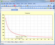
The shape of the Danley curve will vary from one design to another, depending upon the horn throat area and the angle of the cone. If you had the correct curve for a given conical horn, how would you then use that information to position the driver?
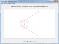
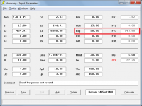
The attached curve is for a test conical horn having S1 = 100 sq cm, S2 = 10000 sq cm and L12 = 100 cm (Flare tangent angle = 26.92 degrees).
One of the principles of the Synergy horn is that the mid and woofer drivers be introduced in a conical horn, where the flare rate corresponds to the respective driver's pass band. If one knows the flare cut off frequency along the axis, the position of the drivers can be known much easy and quick.
Even for the FLH, BLH and Offset horns, parabolic and conical profiles are easier to manufacture, compared to exponential profile. Ability to display the cut off frequency both in the main page and the L12, L23 etc. sliders in the loudspeaker wizard is quite helpful.
And yes, the excel sheet you developed to display the cut-off frequency is the kind of tool I was searching around for.
😂🤣😂🤣
As an additional toggle when cycling through con/exp/par, obviously (possibly in red like the S1-5 stepped expansion). I know its a big ask and to be fair this is already such a cool addition with loads of potential applications!
Hi David,
A questions, up to which frequency the simulation is correct?
I'am simulating a full-range MLTL with the Dayton RS100-8 and I obtain this results:
The valley in the region of 600Hz that is present in the simulation, will be present also in the real speaker? Because in the real TL will be not straight.
Thank you very much!
If you switch the Combined to Combined 1 - what do the other responses show?
Is it possible to switch the expansion off and just have it as a simple additional segment?
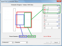
Your diagram shows Throat Port 2 stepped approximately halfway along its length. Just to clarify, is this what you really want, or are you actually asking for the arrangement shown in the attachment below? If the latter, then it should not be too difficult to implement. A Cyl (for cylindrical) option would simply be added to the existing Vrc, Con, Exp and Par options, with Ap2 being the cross-sectional area of the Throat Port 2 cylinder, and Cyl being its axial length.
Attachments
Ability to display the cut off frequency both in the main page and the L12, L23 etc. sliders in the loudspeaker wizard is quite helpful.
I will have to give it some thought...
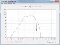
In the attached test example the exponential cutoff frequency of the second conical segment is 143.68 Hz, which seems to match the predicted power response low frequency roll-off point reasonably well.
And yes, the excel sheet you developed to display the cut-off frequency is the kind of tool I was searching around for.
It doesn't seem to be particularly useful indicator though
") . The Danley chart for the attached test example gives a cutoff frequency of 305.58 Hz at a length of 15 cm.
. The Danley chart for the attached test example gives a cutoff frequency of 305.58 Hz at a length of 15 cm.Attachments
Your diagram shows Throat Port 2 stepped approximately halfway along its length. Just to clarify, is this what you really want, or are you actually asking for the arrangement shown in the attachment below? If the latter, then it should not be too difficult to implement. A Cyl (for cylindrical) option would simply be added to the existing Vrc, Con, Exp and Par options, with Ap2 being the cross-sectional area of the Throat Port 2 cylinder, and Cyl being its axial length.
Apologies, I'd not noticed my mistakes when I first posted that image but yes, you're spot on. A Cyl option would give people working with constant CSA stepped expansions in a throat port model essentially an entire extra segment to play with.
A Cyl option would give people working with constant CSA stepped expansions in a throat port model essentially an entire extra segment to play with.
Thanks for the clarification. If all goes according to plan the Cyl option will be included in the next update.
It doesn't seem to be particularly useful indicator though
I'd guess the assumed axial length, input/output diameter and possibly the profile shape might explain the discrepancy.
What is the method you used to calculate the curve?
Thanks for the clarification. If all goes according to plan the Cyl option will be included in the next update.
You Mr McBean are my absolute hero.
It doesn't seem to be particularly useful indicator though
As David has mentioned, conical horns don't have a cutoff the same way as exponential horns do. What is usually considered the "cutoff" of a conical horn is the point where the acoustical resistance at the throat equals the reactance. This happens at
f = c / (2*pi*(X+X0)) [eq. 1]
where
c = speed of sound
X0 is the distance from the apex of the cone, X is the distance from the throat. X0 can be found as
X0 = L / (sqrt(Sm/St) - 1) [eq. 2]
where L = horn length, Sm = mouth area, St = throat area.
These equations should be easy to program in a spreadsheet.
[eq. 1] shows how the "cutoff frequency" varies along the horn, getting lower as you move away from the throat. For an exponential horn the cutoff is constant along the horn, so if you're using an exponential segment to check the cutoff of a conical segment, it's not given that you will get the same value.
I don't believe Danley meant this to be more than a guideline to help you get in the ballpark, the conical horn "cutoff" is very gentle.
This insight is quite helpful. Thanks.
In the attached test example the exponential cutoff frequency of the second conical segment is 143.68 Hz, which seems to match the predicted power response low frequency roll-off point reasonably well.
I have done some further tests and the "C to E" method seems to hold up quite well. At the very least it gives a reasonable idea of where the low frequency roll-off is likely to be. The feature will be added in the next update on the understanding that the cutoff frequency values shown are to be considered as indicative only.
Your diagram shows Throat Port 2 stepped approximately halfway along its length. Just to clarify, is this what you really want, or are you actually asking for the arrangement shown in the attachment below? If the latter, then it should not be too difficult to implement. A Cyl (for cylindrical) option would simply be added to the existing Vrc, Con, Exp and Par options, with Ap2 being the cross-sectional area of the Throat Port 2 cylinder, and Cyl being its axial length.
I can see that working well in a Keystone/Karlson type TH fold where you could possibly put L12 at .01cm...that would switch the end of Vtc/Atc and S1 into the driver entry point.
Last edited:
I have done some further tests and the "C to E" method seems to hold up quite well. At the very least it gives a reasonable idea of where the low frequency roll-off is likely to be. The feature will be added in the next update on the understanding that the cutoff frequency values shown are to be considered as indicative only.
That's great news, David. Looking forward to the next version of Hornresp. Thanks.
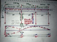
did a tapped pipe (TH1 with red segments)just break into ‘3rds’ on the ‘front’ side entry (VTC/Atc, Ap1/Lp and Ap2/Lp ) of a driver in a long pipe with the motor side entry placed at the velocity max (and thus the pressure max of a second pipe formed (as two parts in the (TH1 L34,L45), and also with an offset -pipe or (surge tank/filter regulator/absorber-) pipe sitting at the mid point of that two pipe junction in the system (as L12 stuffed unstuffed 0 to 999 units in wizard)? And shaped to suit the need or not used at all, but definitely helps if this pipe is a system and the driver excursion is in control here).
It seems that the repetition of an 80 cm length (used as segments with 80 cm or as 160 cm together, as 240 cm total(in each pipe) is the an awkwardly weird (in a good way) to fold and create, yet is mysteriously profound in the response character in dB and response ripples(its smooth and powerful)???
(Its similar as I use 90 or 100cm , 270
Or 300 total) for another driver with a lower Fs and similar motorforce and Vas and the results are also strangely in a window of opportunity? Or pretty close to ‘best possible result for such in a qw based design?)
Is this playing on the stacking of a harmonic or a pressure/velocity difference in the course through the lengths for a pipe physics? Im a little rusty on my sciense stuff but a thermoacoustic motor runs ‘perfect’ at the 1/3 offset to the closed end. Heat Firing at a pipe and pulses form that drive it if the cooling cycle is provided after that location exactly(and ‘bounce’ in the phase off the clised end pressurewave drives it?) But that length is probably not needed in a transducer pulse repeating at those intervals either(80 cm in 240cm in this case, or its double as 160cm) but causes a nice looking result in an offset driver sim. Or is this just a coincidence of fractions that are similar and workout ib the application in the TH mode? Would looking at phase or using another mode to investigate what might be happening show this?
I cant telll if its folding or the two pipes at 90/180/90/360 when offset or from opposite sides of the cone as plotting them with an air column calculator i think i can breakdown the offset driver version, but loose my brain in the TH or compound Horn phase from ADD like haze(math), lol...
————————————side note:
I gotta tell ya David, even if im out in left field here on designs and/or chasing ideas or things that dont even work or could be horns or pipes(my acoustical knowlege is in its infancy??) this is possibly the most exciting pastime, and process to a goal and then Subsequently the next one and then (repeat, repeat each step of the way) and that adventure, ive ever experienced indoors or just in the garage/shop!! You keep opening new doors and allowing more and more things that inspire and are inspiring others in a domino affect here and it is spreading and building in the DIY sectors all over the universe! its the anticOVID and no doubt a major influense in the escape from stressors for many people in the last year or more. This shows in the increasingly willingness to learn it by more and more people.
Your the conductor on a train full of freedom thats an orchestra of speakers all singing the same song... and people are better because of it.
I cant help but notice this. Its spreading it seems
Attachments
Acoustic Energy & Surprising Ways To Harness It (Intro To Thermoacoustics) - YouTube
Might apply as a useful design tool for many ideas as ‘pipes’ in pressure wave phase n 1/3-2/3 affectively the midpoint in a pipe with a closed end
Might apply as a useful design tool for many ideas as ‘pipes’ in pressure wave phase n 1/3-2/3 affectively the midpoint in a pipe with a closed end
What is the method you used to calculate the curve?
Assuming that we have a conical horn defined by S1, S2 and L12:
R1 = Sqrt(S1 / Pi)
R2 = Sqrt(S2 / Pi)
The radius Rx at a distance x from the conical horn throat is given by:
Rx = R1 + x * (R2 - R1) / L12
The cutoff frequency of an exponential horn is given by:
fc = m * c / (4 * Pi)
Where:
m = 2 * Ln(R2 / R1) / L12
c = velocity of sound
I simply calculated the radius values at regular distances along the conical horn axis, and then used adjacent values to calculate fc at a specific point.
To illustrate - in my Post #11745 example to find fc at a distance of 15 cm:
Given:
S1 = 15 sq cm
S2 = 6000 sq cm
L12 (Con) = 65 cm
Then:
R1 = 2.18510 cm
R2 = 43.70194 cm
Conical horn radius at a distance of 14 cm:
R14 = 2.18510 + 14 * (43.70194 - 2.18510) / 65
R14 = 11.12719 cm
Conical horn radius at a distance of 15 cm:
R15 = 2.18510 + 15 * (43.70194 - 2.18510) / 65
R15 = 11.76591 cm
Axial distance between the two = 1 cm
fc = (2 * Ln(11.76591 / 11.12719) / 1) * 34400 / (4 * Pi)
fc = 305.58 Hz
The above technique gives results that are more than adequate for the purpose. If however greater accuracy is required for some reason, then to find fc at a distance of 15 cm, calculate the two radius values at 14.99 and 15.01, with the axial distance between the two being 0.02.
Your the conductor on a train full of freedom thats an orchestra of speakers all singing the same song... and people are better because of it.
Stop it, you're making me blush
.Seriously - thank you. Knowing that Hornresp is valued by users is "music to my ears" (pun intended)
.What is usually considered the "cutoff" of a conical horn is the point where the acoustical resistance at the throat equals the reactance. This happens at
f = c / (2*pi*(X+X0)) [eq. 1]
where
c = speed of sound
X0 is the distance from the apex of the cone, X is the distance from the throat.
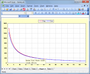
The attachment below compares the Danley curve for the previous example I posted using fc (Exp), against the curve generated using the generally accepted fc (Con) formula, as given by Bjørn.
Attachments
Last edited:


- Home
- Loudspeakers
- Subwoofers
- Hornresp