Why do you need to check the cutoff frequency of an "exp" profile, when a "par" or "con" profile is being used?
As I understand, synergy horn drivers must be introduced along the axis of the horn where the flare rate is lower than the intended high pass frequency of the driver. So, it's useful to know the flare cutoff for the given part of the section.
Only when the profile is changed to "exp" is the cutoff displayed. So, I change the profile from "con" to "exp" to get the cutoff frequency.
The significance of OD in 'Atc & Vtc = OD S1-S2' and 'Ap1 & Lp = OD S2-S3'.
It seems to me that you want to reallocate the tapped horn variables as follows:
S1 = Atc
S2 = Ap1
S3 = Old S1
S4 = Old S2
S5 = Old S3
S6 = Old S4
S7 = Old S5
L12 = Vtc
L23 = Lp
L34 = Old L12
L45 = Old L23
L56 = Old L34
L67 = Old L45
Is this correct, and if so, where is the driver now positioned in the tapped horn?
At Ap1 (throat) and Old S4 (mouth).
Only when the profile is changed to "exp" is the cutoff displayed. So, I change the profile from "con" to "exp" to get the cutoff frequency.
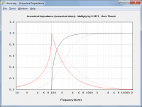
The cutoff frequency is only applicable to the exponential profile. It is not relevant to the conical profile you are actually using. To illustrate, the attached chart compares the throat acoustical impedance of an infinite exponential horn (two dark traces) to that of an equivalent infinite conical horn (two light traces). Notice how the exponential horn has a clearly defined cutoff at 100 hertz, below which the acoustical resistance (black trace) is zero. The conical horn does not exhibit this behaviour - it has no clear cutoff frequency.
I suspect that you would be better off not worrying about cutoff frequencies, and simply adjusting the L12 length slider with S2 set to Auto until an optimum response is obtained 🙂.
Attachments
At Ap1 (throat) and Old S4 (mouth).
Re-purposing the Vrc, Lrc, Ap/Ap1, Lpt/Lp, Vtc and Atc parameters to enable additional in-line tapped horn segments to be specified would require a massive re-write of large parts of the program. Simply using Vrc and Lrc to insert a flared section between the outlet of the existing cylindrical throat chamber port tube and the throat-end inlet to the tapped horn, as requested by thomgiles, has required more than 90 changes. This is as far as I am prepared to go 🙂. In other words, no additional segments!
Oh that's a lovely dirty hack
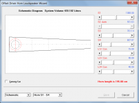
Out of interest I decided to compare the results obtained using the multiple entry model with L23 set to 0.10 (effectively co-locating the two drivers) against those produced by an identical OD model having two drivers connected in parallel. Pleasingly, the results are essentially the same, cross-validating both models even though they are structured completely differently.
Attachments

Why do you need to check the cutoff frequency of an "exp" profile, when a "par" or "con" profile is being used?
The cutoff frequency is only applicable to the exponential profile. It is not relevant to the conical profile you are actually using. To illustrate, the attached chart compares the throat acoustical impedance of an infinite exponential horn (two dark traces) to that of an equivalent infinite conical horn (two light traces). Notice how the exponential horn has a clearly defined cutoff at 100 hertz, below which the acoustical resistance (black trace) is zero. The conical horn does not exhibit this behaviour - it has no clear cutoff frequency.
I suspect that you would be better off not worrying about cutoff frequencies, and simply adjusting the L12 length slider with S2 set to Auto until an optimum response is obtained 🙂.
The advice of finding out the cutoff frequency by changing to the exp profile was from the synergy discussion threads here. Probably a quick and dirty trick.
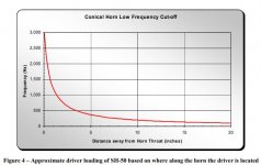
But Tom Danley's explanation of his Synergy patent too has a graph depicting the low frequency cut-off for his conical horn.
I was, in fact, I was searching for a simple tool that would produce a graph similar to that of Danley's paper for a given conical/parabolic profile, so that one can know the placement of drivers easily. 🙂
Attachments
There is never any misleading information in a patent. Nor is there ever any drawings or pictures that may, or may not be subject to the normal physical world.
I look at a lot of patents. Some of them are near complete fantasies.
I'm not saying that Tom's patent is fraudulent. But be careful what you take as complete truth on any patent that you see.
I look at a lot of patents. Some of them are near complete fantasies.
I'm not saying that Tom's patent is fraudulent. But be careful what you take as complete truth on any patent that you see.
There is never any misleading information in a patent. Nor is there ever any drawings or pictures that may, or may not be subject to the normal physical world.
I look at a lot of patents. Some of them are near complete fantasies.
I'm not saying that Tom's patent is fraudulent. But be careful what you take as complete truth on any patent that you see.
If you are referring to the cone horn low cut off graph from Tom's explanation of his Synergy patent, I'm beginning to wonder if the plot is a result of considering an infinitesimally small axial section dz to approximate an exponential profile (a reasonable assumption) and then proceeded to Integrate it over the whole axial length.
Re-purposing the Vrc, Lrc, Ap/Ap1, Lpt/Lp, Vtc and Atc parameters to enable additional in-line tapped horn segments to be specified would require a massive re-write of large parts of the program. Simply using Vrc and Lrc to insert a flared section between the outlet of the existing cylindrical throat chamber port tube and the throat-end inlet to the tapped horn, as requested by thomgiles, has required more than 90 changes. This is as far as I am prepared to go 🙂. In other words, no additional segments!
Got it!
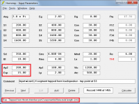
Looking at this pic, looks like Vtc & Atc COULD be 2 segments in a TH. Driver entry point could be half of ATC. Exit point could be S3 or S4.
Attachments
I seem to have found an issue in Hornresp - if the Lpt value is 15.2 or higher - the fundamental frequency is reported at 18.8Hz (!!!).
If Lpt is 15.1 or lower, the fundamental frequency jumps to 53.3Hz.
This is related to filling - if you lower the quantity of fill, then the "trigger" length of the Lpt goes down. I lowered the fill in a couple of sections, and the port can be shortened - and if this is accurate, then I will BUILD IT!
Attachments

Last edited:
Hornresp Update 5140-210219
Hi Everyone,
CHANGE
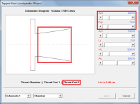
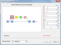
For tapped horns with a throat chamber port, double-clicking on the Lrc label in edit mode now specifies a second throat port connected in series with the first. Throat port 2 can have a conical, exponential or parabolic flare. Attachments 1 to 3 refer.
BUG FIX
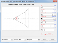
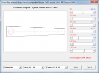
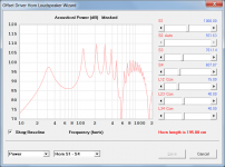
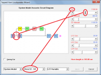
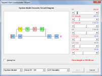
After the stepped segment feature was added to the loudspeaker wizard, errors could sometimes occur in the positioning of the sliders and in the operation of the System Model. These problems have now been fixed. Attachment 4 shows an example of what could happen before the problem was fixed (S4 slider where the S1 slider should be and System Model S4 red area marker lines incorrectly located). Attachment 5 shows the same screen with the problem fixed (S1 and S4 sliders and System Model S1 red area marker line now all correctly located).
Kind regards,
David
Hi Everyone,
CHANGE
For tapped horns with a throat chamber port, double-clicking on the Lrc label in edit mode now specifies a second throat port connected in series with the first. Throat port 2 can have a conical, exponential or parabolic flare. Attachments 1 to 3 refer.
BUG FIX
After the stepped segment feature was added to the loudspeaker wizard, errors could sometimes occur in the positioning of the sliders and in the operation of the System Model. These problems have now been fixed. Attachment 4 shows an example of what could happen before the problem was fixed (S4 slider where the S1 slider should be and System Model S4 red area marker lines incorrectly located). Attachment 5 shows the same screen with the problem fixed (S1 and S4 sliders and System Model S1 red area marker line now all correctly located).
Kind regards,
David
Attachments
if the Lpt value is 15.2 or higher - the fundamental frequency is reported at 18.8Hz (!!!).
If Lpt is 15.1 or lower, the fundamental frequency jumps to 53.3Hz.
Hornresp determines the system fundamental frequency from an examination of the electrical impedance and diaphragm displacement data. In some borderline cases the algorithm can get "confused", and it is possible for the displayed resonance frequency value to "jump" when a slight alteration is made to an input parameter value. If this happens it is necessary to examine the electrical impedance and diaphragm displacement charts manually, to determine where the resonance frequency lies.
Post #10383 linked below also refers.
https://www.diyaudio.com/forums/subwoofers/119854-hornresp-1039.html#post6045006
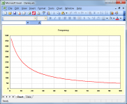
I was searching for a simple tool that would produce a graph similar to that of Danley's paper for a given conical/parabolic profile, so that one can know the placement of drivers easily.
Thanks for the links. I will have a read when I get a chance to see if I can work out what it all means, and if it would perhaps be possible to include something in Hornresp...
I was searching for a simple tool that would produce a graph similar to that of Danley's paper for a given conical/parabolic profile, so that one can know the placement of drivers easily.
The shape of the Danley curve will vary from one design to another, depending upon the horn throat area and the angle of the cone. If you had the correct curve for a given conical horn, how would you then use that information to position the driver?
The attached curve is for a test conical horn having S1 = 100 sq cm, S2 = 10000 sq cm and L12 = 100 cm (Flare tangent angle = 26.92 degrees).
Attachments
Last edited:
Hi Everyone,
CHANGE
For tapped horns with a throat chamber port, double-clicking on the Lrc label in edit mode now specifies a second throat port connected in series with the first. Throat port 2 can have a conical, exponential or parabolic flare. Attachments 1 to 3 refer.
Kind regards,
David
NICE update!!!!
Hi Everyone,
CHANGE
For tapped horns with a throat chamber port, double-clicking on the Lrc label in edit mode now specifies a second throat port connected in series with the first. Throat port 2 can have a conical, exponential or parabolic flare. Attachments 1 to 3 refer.
BUG FIX
After the stepped segment feature was added to the loudspeaker wizard, errors could sometimes occur in the positioning of the sliders and in the operation of the System Model. These problems have now been fixed. Attachment 4 shows an example of what could happen before the problem was fixed (S4 slider where the S1 slider should be and System Model S4 red area marker lines incorrectly located). Attachment 5 shows the same screen with the problem fixed (S1 and S4 sliders and System Model S1 red area marker line now all correctly located).
Kind regards,
David
This is amazing. I actually never though this would get through triage. Im sure there are loads of people who will make use of this (in particular the paraflex development community) so on their behalf I would like to say a massive thankyou. 🙂
One more (hopefully minor) thing? Is it possible to switch the expansion off and just have it as a simple additional segment? So instead of Ap1->Ap2 functioning like either a conical, parabolic etc expansion it instead functions as two separate stepped sections (i.e. Lp2)? Sorry to ask!

Last edited:
Hornresp determines the system fundamental frequency from an examination of the electrical impedance and diaphragm displacement data. In some borderline cases the algorithm can get "confused", and it is possible for the displayed resonance frequency value to "jump" when a slight alteration is made to an input parameter value. If this happens it is necessary to examine the electrical impedance and diaphragm displacement charts manually, to determine where the resonance frequency lies.
Post #10383 linked below also refers.
https://www.diyaudio.com/forums/subwoofers/119854-hornresp-1039.html#post6045006
Thank you, David once again! I can understand that this is how it works - and you have mentioned that greater amounts of filling become difficult to model as accurately.
The good news is that I needed to reduce the filling, and this takes the model back from this threshold - and the fundamental frequency is a fabulous 20.7Hz! I am going to continue to see if I can lift the portion of the response below ~180Hz by 1-2dB.
One more (hopefully minor) thing? Is it possible to switch the expansion off and just have it as a simple additional segment? So instead of Ap1->Ap2 functioning like either a conical, parabolic etc expansion it instead functions as two separate stepped sections (i.e. Lp2)? Sorry to ask!
😂🤣😂🤣
- Home
- Loudspeakers
- Subwoofers
- Hornresp