Hi Sandro,
I do know, but do not have the time to get drawn into a discussion that is really a defense of what I have stated.
The easiest way for you to figure this out is to try it. You can discuss and defend something until the cows come home without reaching a conclusion. So invest the time you would spend debating the issue and try this with real parts. If you haven't access to the equipment and parts, then it would have been a purely academic debate - a complete waste of my time and yours. So if it matters to you, experiment.
My work is on public display, so the last thing I need to do is run and hide from your questions. I'm trying to point you in the right direction to save you some time.
-Chris
Hi Chris, I do not understand why you think I am attacking your position. I have said 3 times already, I am not questioning your results/observations... I have no reason to not believe you. What I would like to know, is the technical root cause behind your observations.
If you know the root cause behind your observations (which you just said you do) I am asking you to pretty please share. Sharing is the whole point of a forum.
Now, if you are telling me to not post back if you give me an answer I don't agree with, fair enough, your choice and I respect it.
- Sandro
Hi Sandro,
Okay, imagine a device has a beta of 60 (reasonable for an output) and another is about 45, again a reasonable spread. The emitter resistor is 0R33. The target bias current is 60 mA and the resistor tolerance is 10%. Assume the higher gain device conducts 60 mA. Figure out what the other device is conducting assuming approx equal base current. Now, consider a resistor and look at how much voltage is dropped when you look at it being bang on, then 10 % high and low. What's the range in mV? Now consider VBE mismatch of a few mV.
You'll see that VBE is swamped by other circuit factors.
-Chris
Hi Chris,
If the base currents are roughly the same, yes the currents will split according to the beta ratio. But, in an EF output stage (or CFP for that matter), the base currents in the output devices are not forced to be equal, hence, they won't be. So, this is not a real world assumption.
Now, what I am missing, is where does Beta enter in all of this? I know I am being pushy, but, that is how engineering works. Engineers don't rest until we get a stisfactory answer or an 'I don't know', and I have all the good and bad traits of an engineer. Worse, I have the ones of an IC designer.
Okay, imagine a device has a beta of 60 (reasonable for an output) and another is about 45, again a reasonable spread. The emitter resistor is 0R33. The target bias current is 60 mA and the resistor tolerance is 10%. Assume the higher gain device conducts 60 mA. Figure out what the other device is conducting assuming approx equal base current.
If the base currents are roughly the same, yes the currents will split according to the beta ratio. But, in an EF output stage (or CFP for that matter), the base currents in the output devices are not forced to be equal, hence, they won't be. So, this is not a real world assumption.
I agree that there is a strong influence of RE (the 0.33 ohm) on the current split and it over-rides VBE mismatch. No need to do the experiment, I know this is the case. This is whole reason for RE to exist. With sufficient Voltage across RE, the split is completely dictated by RE mismatch.Now, consider a resistor and look at how much voltage is dropped when you look at it being bang on, then 10 % high and low. What's the range in mV? Now consider VBE mismatch of a few mV.
Now, what I am missing, is where does Beta enter in all of this? I know I am being pushy, but, that is how engineering works. Engineers don't rest until we get a stisfactory answer or an 'I don't know', and I have all the good and bad traits of an engineer. Worse, I have the ones of an IC designer.
The beta will cause a current mismatch and amplify the drop across the emitter resistor one way or the other. More than VBE will.. That's my point. Beta also changes faster than VBE with temperature. Beta also doesn't care about the resistor value, but tends to increase with current at lower currents.
When you have paralleled outputs, the voltage presented to the base - emitter will be close to the same for each device. The biggest variation will be current differences creating a different voltage across the emitter resistors. That will change VBE to partially compensate for low beta. However, in practice the beta spread can be wider than my example and this really matters at high currents where the emitter resistors will have a much higher, but more equal drop across them. At higher currents, the resistors set the current sharing. Large beta differences can still create sharing issues. At low currents the beta dominates and really affects performance around the zero crossing. VBE just doesn't ever come into being a dominant factor.
This may be different in an IC, I don't know. I understand that transistors on a die will have similar characteristics assuming the masks are the same. But the world on a die is a bit different than large discrete parts simply because they are on their own die, so they don't have that same natural matching, but more importantly, the thermal environment each device is in tends to be different. That changes everything. Therefore it comes down to current flow as well as heat sink position. Current flow depends greatly on beta and emitter resistance, temperature modifies beta greatly which amplifies beta differences. Without emitter resistors you would quickly run into current hogging and thermal runaway with large numbers of unmatched parts. Say a BGW 750C that uses 6 outputs for each polarity (or is it 5?). Problems aren't usually that bad with a a pair of outputs unless they are way out of match.
There's a lot more I can get into, but that is more time than I can spend on this. I'm trying to relay concepts and the broad idea.
-Chris
Current flow depends greatly on beta and emitter resistance, temperature modifies beta greatly which amplifies beta differences.
I believe our disagreement is fundamental. You are convinced that the output devices, the emitter current is a strong function of base current and hence Beta. I completely disagree. I believe that:
- The total is function of load current at higher currents and bias current at zero current.
- The split is a function of RE (heavy) and VBE (medium to low depending on RE value)
- Beta (small) mostly through rb voltage drops.
Why? Because the output stage devices are driven by a voltage and not a current.
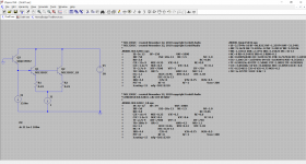
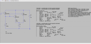
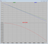
Here is a sim to show my believe.
Setup:
- Output stage of Honey Badger amplifier, heavily simplified.
- Q1 has a beta of 158 (nominal), Q2 has a beta of 79 (halved). The models are on the left of the schematic.
- Q3 is a pre-driver biased at 13.8mA, same as Honey Badger.
Simulation:
- Sweep load current from 0 to 1 Amp.
- Monitor all currents.
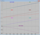
Results:
- Base current of Q1 is half of Q2, makes sense since Beta is half.
- Emitter currents are 36mA off from each other at 1A load current (3.6%) even though beta mismatch is 2x.
Conclusion: Beta is not a strong factor in current split.
Attachments
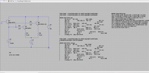
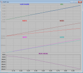
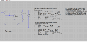
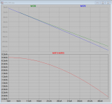
Now I repeated the experiment, added 2.2 ohm base resistors. Expectation is that split mismatch will get worse from my theory:
Results: At 1 Amp, mis-match went from 36mA to 55mA.
Conclusion: Theory is correct, expected results seen, but 55mA (5.5%) mismatch for a 2x mismatch in beta is not a huge concern.
Sandro said:
"Beta match is important too because of the output device base resistors. Look at the HoneyBadger amplifier, each output device has 2.2 ohm base resistor. The voltage drop across these adds to VBE since the output devices are biased with a fixed VBIAS spreader. Therefore, if beta mismatches you are indirectly adding VBE mismatch to each device, which takes us to the previous paragraph."
Results: At 1 Amp, mis-match went from 36mA to 55mA.
Conclusion: Theory is correct, expected results seen, but 55mA (5.5%) mismatch for a 2x mismatch in beta is not a huge concern.
Attachments
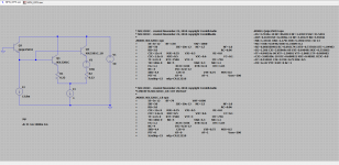
Now let's do a final experiment, mis-match RE by 2x (0.22 for RE1 and 0.11 for RE2) and run the experiment. I know this is gross, but I am trying to prove something:
A. Matched trasistors, only RE's mismatch.
B. Beta mis-matched transistors and mismatched Betas.
Results:
A. Matched transistors: IE1 and IE2 mismatch by 230mA, or 23% at 1A. This is expected, RE is a strong function of the split.
B. Mismatched transistors: Mismatched increased to 257mA or 25.7% at 1A. An increase of 2.7% over case A.
Conclusion:
Beta does have a neglible dependency even in the face of a strong RE mismatch. 2x beta mismatch caused only a 2.7% change.
Attachments
Last edited:
So, after these experiments, I now more strongly stand on my original comment which started whis whole discussion:
"AKSA is totally on point on this one.
- For same flavor Output devices, matching VBE is by far the most important after matching RE. The more mismatch, the higher the RE needs to be which has other problems. BUT, the most important is to match VBE's over temperature. I.e. the parallel output devices need to be thermally coupled, hence why they are mounted on the same heat sink. Else, temperature differences will cause the VBEs to drift apart, the hotter device will have the smaller VBE, hog all the output current and potentially blow up.
- Beta match is important too because of the output device base resistors. Look at the HoneyBadger amplifier, each output device has 2.2 ohm base resistor. The voltage drop across these adds to VBE since the output devices are biased with a fixed VBIAS spreader. Therefore, if beta mismatches you are indirectly adding VBE mismatch to each device, which takes us to the previous paragraph."
I guess on the last paragraph I gave Beta more importance than it deserves, but oh well, I had not done the sim then.
Thanks Sandro for the simulation work, quite reveilling for me.
But still here I am with my original question.
https://www.diyaudio.com/forums/sol...anssistors-class-tou-match-2.html#post6159938
I again measured the voltages over the 0R22 emitter resistors, this time in cold (18C) and hot (55C) condition. The delta between lowest and highest measurement increased from cold to hot, from 1,6mV to 1,8mV.
With an average bias current of 23mA, I have a mismatch of about 7%, which I’m not that happy about. But I also don’t want to order 100 more bjt’s either if not needed.
Will the mismatch off 7% in emitter current between the output devices have a negative influence on the sound? This amp had about 12W in Class A which is more than I need most of the time.
Regards
Hi Bensen, sorry the discussion got de-railed from your original question. I want to put the results a couple more sims, and then we can discuss. Results are quite revealing.
I love simulation by the way, it is the most controlled way to get insight and prove ideas.
(See my thread SW-VFA-01: Audio power amplifier video series)
I love simulation by the way, it is the most controlled way to get insight and prove ideas.
(See my thread SW-VFA-01: Audio power amplifier video series)
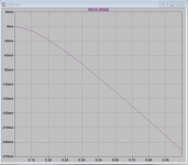
In the previous sims I was comparing at 1Amp, what happens now if we go from 1mA to 50mA, when the RE voltage is small, i.e. much less than KT/q = 25mV.?
Expected result, RE won't matter much due to not having enough voltage to do anything, and we know already that Beta does not matter much.
Setup: Same as in post 28. RE1 = 0.11 and RE2=0.22
Results:
- With matched beta transistors, at 50mA, current is mismatch is 2.2mA or 4.4%
- With unmatched beta transistors, at 50ma, current mismatch is 2.5 mA or 5%
Conclusion
- Results match expectations, at low current RE does not matter much and Beta really does not matter.
So, now the question is, what matters are low currents? VBE, see next experiment!
Attachments
Last edited:
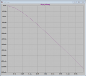
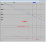
What matters are low currents? What determines the ratio of currents?
Expectation: VBE match
Setup is similar, RE are matched and I introduced an 18mV VBE mismatch. This is a grosse mis-match but it is for illustration purposes.
Expected behavior:
- At low current, ratio of IE_Q1 and IE_Q2 = exp(DELTA_VBE/(KT/q)) = exp(18mV/26mv) = ~2 purely due to the 18mV delta vbe introduced.
- As current increases, IE_Q2/IE_Q1 approaches RE1/RE2 = 1
Results:
- With beta matched and mismatched: In both cases the current ratio goes from ~2 to ~1 as predicted.
- In the beta mismatch case, it is approaching 1 more slowly.
Conclusion: At low currents, VBE mismatch determines the ratio and beta does not matter in a substantial way.
Attachments

Last edited:
CONCLUSIONS
So after all these experiments, I can conclude the following:
- At low current VBE determines current ratio
- At high currents RE determines ratio
- Beta plays a small part due to IB*(rb+R_base_stopper) voltage drops affecting VBE
RECOMMENDATIONS
Nothing that goes much beyond AKSA's original recommendation:
- Match VBE in transistors, within a 1mV is good
- Match RE's, get 5% tops. Pay for 1% if you can.
- Have beta close within reason, <=10%, but do not stress out.
Enjoy!
- Sandro
Now Bensen, see if you can figure out what is going on based on these results:
Things to check:
- RE Resistor ratio
- VBE match
- Current ratio at quiescent
- Current ratio at 1A
Measure each VRE at quiescent and at 1A. I think with those measurements, we can figure it out.
Also, post a schematic.
Best, Sandro
Things to check:
- RE Resistor ratio
- VBE match
- Current ratio at quiescent
- Current ratio at 1A
Measure each VRE at quiescent and at 1A. I think with those measurements, we can figure it out.
Also, post a schematic.
Best, Sandro
Hi John,
I completely agree with you with regard to matching.
Also consider the crossover point in the waveform. Your emitter resistors will not generate enough voltage drop to reinforce current sharing. The outputs will turn off at different times.
Some transistor compliments match closer than others. This is where the Japanese parts were superior to the US ones. They were faster too (as everyone knows) with a flatter gain vs current curve.
-Chris
The outputs will always turn off at the same time (within nS) due to feedback. If they didnt you would be getting a voltage out when one wasn't required.
In 40 years I have never matched transistors even in amps with multiple output pairs. The right emitter/source resistors do the job.
If you are buying transistors from same batch then they are probably pretty close anyway.
The only time I have seen problems is replacing 1980 transistors with modern versions. Sometimes the gain is higher and they have a wider bandwidth than the originals. I got caught out with modern 2n3055/MJ2955's. Had to increase VAS cap to allow for differences.
Hi Sandro,
You simulated these results. The models are based on VBE, so I'm not at all surprised they supported your viewpoint.
Try it with real devices as I had recommended way back at the beginning. I knew what the sims would point to.
Unlike what you have done, I actually bought and paid for hundreds of transistors, thousands if you count signal devices. Then I bought the test equipment and spent decades using it. My current meter is a Keysight 34465A, but the earlier ones I used should be good enough, they are 34401A meters and I bought that when it first came out and added more over the years. I also spent time in an instrument calibration lab and became a journeyman calibration technician in addition to normal audio technician experience.
Maybe I have the exact mechanism wrong, but the measured results aren't. Also, Motorola discovered that matching the outputs can reduce distortion before feedback by 20 dB. Those guys are far more experienced than either of us I would guess. Their equipment budget is also much, much higher than mine.
At the end of the day, you put all your eggs in the simulator basket. As long as your creations are only simulated, you're doing fine. But the real world isn't always accurately reflected by simulators. But I guess you are comfortable with the idea the equipment I'm using must be faulty given that I relied on one manufacturer (HP / Agilent ? Keysight). Given that that equipment is what was used to find matches, and to measure the results over decades, all I did was apply the connections and record the numbers. No interpretation was required.
As I feared, this was a complete and utter waste of time given that you fell back on simulation after I told you to actually measure things. Had you been honest and told me you had no intention of actually investing a little time and would use a simulator I could have told you what you would find and saved a great deal of time for both of us. This is why I was reluctant to play your game to begin with.
-Chris
Hi Nigel,
Maybe if you had invested the time to create proper matches you would have seen a difference. I have measured reductions in distortion from matching the parts in the output stage, and more importantly in the diff pair stage(s).
Feedback does not force all the outputs to cease conducting at the same time if you have mis-matches. That assumption doesn't hold water simply because the error amp sees the output stage as a black box. It doesn't "see" individual outputs and couldn't control them individually anyway.
You've never had a problem that you know of, nor have you been able to increase distortion performance. But then you would need a higher performing THD meter to illustrate the effects I am talking about. What instrument are you using?
-Chris
What in the world does that mean? Are you saying those models are wrong? If you are, then e-mail Bob Cordell since they are his models and he would be interested in knowing you think they are wrong.The models are based on VBE
If simulation did not give good results, then there would be no IC industry were ALL products are designed on simulation and then fabbed and tested. So, while simulation is not always 100% accurate, it will not mess up basic things like VBE, IB and BETA behavior. Where a simulator messes up is on fineline measurements like say sim may say THD is 0.0001% and you measure 0.0003%.At the end of the day, you put all your eggs in the simulator basket. As long as your creations are only simulated, you're doing fine.
Now if you are going to tell me that ICs are different than amplifiers, well, what I can I tell you... they are not. The underlying physics are the same.
But, if you can point out what in my sims is not being captured, I would be interested in knowing.
Nope, never said that, nor implied it. I actually know those guys, they were my customers when I was ADI, along with Tektronix and National Instruments. Great guys who make great products.But I guess you are comfortable with the idea the equipment I'm using must be faulty given that I relied on one manufacturer (HP / Agilent ? Keysight)
Maybe than you, I was a senior design engineer at ADI when I left the company, so I would say I am at par.Those guys are far more experienced than either of us I would guess
I figured you did not know the underlying mechanism even though you said you did. I would encourage you to try to figure out what is the underlying mechanism so we can have a more meaningful conversation if you are interested, which I doubt at this point.Maybe I have the exact mechanism wrong
Maybe a waste of time for you, but not for me. I enjoyed the experiments I did in the simulator and they proved enlightening. Sorry you did not learn anything out of it, Benser and I did.As I feared, this was a complete and utter waste of time given that you fell back on simulation after I told you to actually measure things. Had you been honest and told me you had no intention of actually investing a little time and would use a simulator I could have told you what you would find and saved a great deal of time for both of us. This is why I was reluctant to play your game to begin with.
Actually building the simulated circuit would have been a waste of time and money since the results in simulation are so strikingly revealing and agreeing with theory. I would have only done it if sim results were inconsistent with theory.
Anyway, good chat and stay safe.
Best, Sandro
Last edited:
Sandro,
You went into this with a desire to disprove what I've been saying, and that's fine. But you weren't honest about your intentions. You wasted my time completely and so therfore I won't agree to discuss this again.
Bob's models as they fit the sim are probably fine. What I said was that simulators don't always reflect real life. There are decades of careful measurements that don't happen to agree with what your premise is. Fine. You refuse to do the actual work and sit on your behind instead of getting your hands dirty. That's fine too. Just be honest about it.
Lastly, the one thing designers say is that you can simulate a circuit, but you have to build the think to be sure it works. I know Bob mostly simulates his circuits, I am not aware of how much he actually builds. Nor do we have his feedback as to how closely his practical circuits match the simulated results. That's all I have said.
I was taught that the BJT was a voltage controlled device, but that didn't match what I was finding. So, while it may be, there are other factors that may not be modeled properly yet. I don't know that answer, so I was forced to work practically with current controlled models. BTW, that is not incorrect either.
Finally, as I stated before, ICs are a special case. You didn't read that I guess. Every IC text book does indicate that semiconductors constructed on one die share special circumstances. Thermal contact and the same chemical makeup being some of the main reasons for this. So your comments on that subject prove you argue from a stance that favors your viewpoint only. I did say that rules that apply to parts on a single die do not hold to individual parts.
I feel you are out to win debates (as I stated earlier) instead of finding out the truth about what is going on. Roll up your sleeves and earn the right to comment as you have. Right now your understanding exists in a make believe world of special circumstances and simulations. Man up and do the actual work Sandro.
Best, Chris
- Home
- Amplifiers
- Solid State
- If you put new output transistors, class A/B, will tou match them?