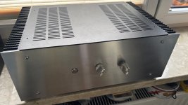
Many thanks Byronin. I got it via AliExpress. I looked long and hard but China was the only source. The cost was around £65ish BUT the postage cost a huge amount...about £100!...in fact things are even more expensive now. I was reluctant but I just gave in and bought it. I have to say it is beautifully made and VERY heavy. It also had pre drilled L/S binding post holes and RCA input holes and also a "kettle plug" power socket hole and plug included...... Search for "Class A amplifier enclosure". My seller hasn't any now. By the way, the white mark on the front panel is white grease I forgot to wipe off....Oh the shame 🙂 PS: All 5 internal power indicator LEDs are crazily bright! PPS: I noticed that I haven't finished it entirely as yet. I might install output coils, but as yet no instability, therefore the speaker output wires are not secured down with ties. Also I might fit polypropylene Input Caps (V4.2 has no DC blocking cap) , but my pre-amp has zero offset so OK. Might leave it without any.That's a very neat and tidy build. Where did you get that chassis?
Last edited:
That's too bad about the shipping. I'm always looking for inexpensive chassis-es
For folks like me, on the West Coast of the USA:
Your chassis: $135.50 + $146.20 = $281.70
Similar chassis from Modushop: $227.89 + $87.73 = $315.62
The one you found is still less expensive, plus it has those pre-drilled holes.
I don't understand how is costs more to ship something from China to the West Coast of USA than to ship from Italy.

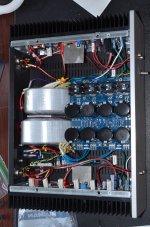
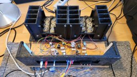
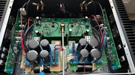
Finally finished setting up both channels bias successfully on KSA-100...One module wired... checked all the voltages, mains, DC Rails, dc offset, speaker protection... all good for testing.
View attachment 1455278
View attachment 1455279
both low and high @ 60mV and 200mV (480mA and 1.6A) respectively. The below readings on high bias.
heat sink temperature... after an hour of playing.
Trafo temperature
junction temp
temp acrylic face plate... need to do some cosmetic finishing on the plates.
provided a toggle switch for low and high bias option...
slow spinning fan on back panel...
...
L12 Amp now with 10uF polypropylene input caps fitted

While it's not a new build, I largely rebuilt my Honeybadger.
The story:
I've been happily listening to my Honeybadger for about 10 years. Then, recently, one of the channels failed. Long story short: I was using the Elliott Sound Products P39 Softstart. It uses a "timing capacitor" to delay switching the relays. The capacitor slowly charges, and when charge reaches a certain level, the relays are tripped taking the series resistors out of the mains circuit. That capacitor failed and became an open. This meant no delay before tripping the relays. I was happily oblivious to this until . . . yeah. 😕 But it's worse than that. When I tested them, both of my transformers had failed. I guess the handling turned a borderline short into a short.
So I figured that as long as I have it all apart, I upgrade everything. Here is what I changed:
I haven't listened to it yet or tested it yet . . .
The story:
I've been happily listening to my Honeybadger for about 10 years. Then, recently, one of the channels failed. Long story short: I was using the Elliott Sound Products P39 Softstart. It uses a "timing capacitor" to delay switching the relays. The capacitor slowly charges, and when charge reaches a certain level, the relays are tripped taking the series resistors out of the mains circuit. That capacitor failed and became an open. This meant no delay before tripping the relays. I was happily oblivious to this until . . . yeah. 😕 But it's worse than that. When I tested them, both of my transformers had failed. I guess the handling turned a borderline short into a short.
So I figured that as long as I have it all apart, I upgrade everything. Here is what I changed:
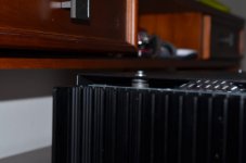
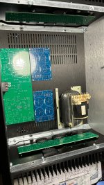
- I moved it from one of the old 4U Antek chassis to a HiFi2000 3U chassis with 10mm brushed aluminum front cover. Sooooooo pretty!🦋
- My new transformers are Antek AS3440. These are the transformers with the "Static Shield" which is supposed to make them quieter. It also makes them bigger.
- I replaced my power supply which I designed myself with a pair of Universal Power supplies from the DIYaudio store. I used 8200uF caps because I got a bargain on a bunch of them trough the Swap Meet.
- I replaced my ESP softstart with the "Soft as a Feather Pillow" unit from XRK Audio. I recommend this softstart to anyone not afraid of SMD soldering. It has a long delay and indicator lights for standby mode and ON.
I haven't listened to it yet or tested it yet . . .
Attachments
L12. my FINAL version. It now includes the output Inductors (about 1.8 mH), They have to hang off the board as there is no space to position them neatly on the board. So, have the 3x mods made any difference to the sound quality? I have to be honest and say I don't think so 🙁 …. Am I happy with the sound?. Well it has some merits, but somehow there is something I'm not so happy with, (compared to the LJM L20 V9.2) The bass is often detailed but often it is not "fluid" and rich, and sometimes it just seems "puffy". Vocals often lack warmth and can sound thin at worst. (this is an mentioned by the sellers on AliExpress!) Maybe I'll get used to it but I'll be keeping an eye out for something else, and currently thinking of going back to my L20 amp.

Testing my old penultimate JLH out from storage. Still works fine.
Attachments
Last edited:

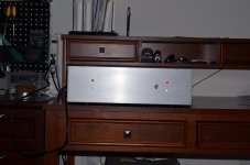
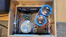
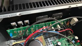
My humble attempt at cloning NAD S300. PCBs drawn by myself. I used modushop enclosure that I had at hand. Drilling done at home.
Temporary power supplies use old Technics SUA600 trafos and capacitors lying around. Speaker protection yet to be added as well as some LEDs.
Sound is extremely transparent , a bit warm and dynamic.
Temporary power supplies use old Technics SUA600 trafos and capacitors lying around. Speaker protection yet to be added as well as some LEDs.
Sound is extremely transparent , a bit warm and dynamic.
Attachments
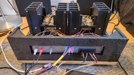
Here's my recent build,TO-3 version of Apex AX14... built on circuit board designed by a friend.

Final Layout

single sided PCB 206.5mm x 116.5mm


Populated and tested modules

...
Final Layout
single sided PCB 206.5mm x 116.5mm
Populated and tested modules
...
- Home
- Amplifiers
- Solid State
- Post your Solid State pics here