EC loop gain
Hi Jan,
Never mind.
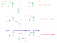
You are right, in that situation, the loop gain is far from infinite. If you don't mind, I've translated your diagram into MicroCap symbols to check and double check a couple of things, and indeed, the loop gain is extreme low, see attachment, fig. 2.
However, if we break the loop at the output side, see fig. 3, than that loop gain is infinite. MicroCap was (of course) complaining about a singular matrix, so I had to alter the gain of the summer (E8) slightly below unity. In this case I observed a loop gain of about 100dB.
As you see, I don't disagree with you, but I only try to demonstrate that there exists a different look at EC circuitry, that's all.
Cheers, Edmond.
janneman said:OK Edmond, I may have been confusing things unnecessary. Apologies.
Hi Jan,
Never mind.
janneman said:I have always said that in my implementation, there is NO ol gain in excess of the closed loop gain. Go ahead, read that again.
In case of my ec power amp, I have published the circuit in the attachment. You will see that the ol gain A = 'about 1'. Then there is the ec 'feedback' to the input summer. What I would think is that 'opening the loop' would be to break that connection from the ec summer to the input summer. In THAT situation, is there 'infinite' loop gain???
[snip]
Jan Didden
You are right, in that situation, the loop gain is far from infinite. If you don't mind, I've translated your diagram into MicroCap symbols to check and double check a couple of things, and indeed, the loop gain is extreme low, see attachment, fig. 2.
However, if we break the loop at the output side, see fig. 3, than that loop gain is infinite. MicroCap was (of course) complaining about a singular matrix, so I had to alter the gain of the summer (E8) slightly below unity. In this case I observed a loop gain of about 100dB.
As you see, I don't disagree with you, but I only try to demonstrate that there exists a different look at EC circuitry, that's all.
Cheers, Edmond.
Attachments
Effect of EC on XO Distortion
In the feedback thread we have been looking at the effect of NFB on output stage crossover distortion. Here I thought that I would show the effect of error correction on crossover distortion.
The simulation includes just a Class-AB output stage pair using the ThermalTrak RET BJTs. They include 0.22 ohm emitter resistors and are biased with 20 mV across each RE.
The stage is feeding an 8-ohm resistor. It is operating at 10 V p-p at 1 kHz.
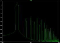
Below I show the output spectra without EC.
Note the scale, which ranges from +20 dB down to -180 dB. The fundamental is at about +10 dB.
As expected, the crossover distortion spectra extends quite far out in frequency, albeit down to about -160 dB by the time it reaches 30 kHz.
Cheers,
Bob
In the feedback thread we have been looking at the effect of NFB on output stage crossover distortion. Here I thought that I would show the effect of error correction on crossover distortion.
The simulation includes just a Class-AB output stage pair using the ThermalTrak RET BJTs. They include 0.22 ohm emitter resistors and are biased with 20 mV across each RE.
The stage is feeding an 8-ohm resistor. It is operating at 10 V p-p at 1 kHz.
Below I show the output spectra without EC.
Note the scale, which ranges from +20 dB down to -180 dB. The fundamental is at about +10 dB.
As expected, the crossover distortion spectra extends quite far out in frequency, albeit down to about -160 dB by the time it reaches 30 kHz.
Cheers,
Bob
Attachments
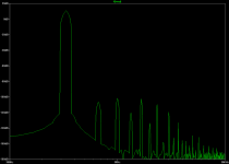
Here on the same scale one can see the very significant reduction of crossover distortion spectra.
The EC circuit is operating at 99%, reflecting a deliberate 1% tolerance error. The distortion levels are lower if no tolerance error is introduced. The bandwidth of the EC loop is at 1.6 MHz, reflecting the usual EC loop compensation that is required.
Again, bear in mind the very wide dynamic range of the scales when making the comparisons.
Cheers,
Bob
Attachments
Re: EC loop gain
Edmond,
I think we are fully in agreement here. If you disconnect the ec signal from the input summer as you did in fig 2, the loop gain shows a very low value. For me that demonstrates clearly that there is no 'hidden' (high) loop gain in an error correction system.
If you break ONLY the negative feedback loop and leave the pos feedback loop intact, one, as expected, finds a very high loop gain because you now have a circuit with only pos feedback. But that's not the ec circuit we were discussing anymore!
What is determining the system behaviour is the EFFECTIVE feedback, which is a combination of pos and neg fb in a specific ratio. That effective feedback is disconnected in fig 2 and shows NO hidden loop gain.
QED, AFAIAC.
PS And thanks very much for the sims!
Jan Didden
estuart said:
Hi Jan,
Never mind.
You are right, in that situation, the loop gain is far from infinite. If you don't mind, I've translated your diagram into MicroCap symbols to check and double check a couple of things, and indeed, the loop gain is extreme low, see attachment, fig. 2.
However, if we break the loop at the output side, see fig. 3, than that loop gain is infinite. MicroCap was (of course) complaining about a singular matrix, so I had to alter the gain of the summer (E8) slightly below unity. In this case I observed a loop gain of about 100dB.
As you see, I don't disagree with you, but I only try to demonstrate that there exists a different look at EC circuitry, that's all.
Cheers, Edmond.
Edmond,
I think we are fully in agreement here. If you disconnect the ec signal from the input summer as you did in fig 2, the loop gain shows a very low value. For me that demonstrates clearly that there is no 'hidden' (high) loop gain in an error correction system.
If you break ONLY the negative feedback loop and leave the pos feedback loop intact, one, as expected, finds a very high loop gain because you now have a circuit with only pos feedback. But that's not the ec circuit we were discussing anymore!
What is determining the system behaviour is the EFFECTIVE feedback, which is a combination of pos and neg fb in a specific ratio. That effective feedback is disconnected in fig 2 and shows NO hidden loop gain.
QED, AFAIAC.
PS And thanks very much for the sims!
Jan Didden
janneman said:Bob, in your last post, the figure doesn't open (it does in the one before that). Is there a problem with the figure?
Jan Didden
Jan, for me it does open.
Re: EC loop gain
Edmond,
Looking one more time at your fig 2. Your sim shows a loop gain of -33.98dB.
As I said, the effective feedback is (1/A)-1. When I plug in your A=0.98, that comes out to about 0.0204. Multiply that by the gain in the forward path, the 0.98. That gives 0.02 for the loop gain.
That, my friend, comes out to -33.979dB. This neatly confirms the validity of using the effective feedback as the criterium to judge amp behaviour, and your method of determining the loop gain. I think we can live with the fact that your sim is 0.001dB off..")
But what does this actually mean, that the loop gain is -33.979dB (or 0.02)? It means that the loop gain is just enough to add the missing 0.02 fraction to the input signal to make the gain appear as exactly '1' instead of the ol gain of 0.98.
You put in 1V, the error correction adds 0.0204V, the gain = 0.98 and out comes exactly 1V. I keep on being surprised by this mechanism.
Jan Didden
estuart said:
Hi Jan,
Never mind.
You are right, in that situation, the loop gain is far from infinite. If you don't mind, I've translated your diagram into MicroCap symbols to check and double check a couple of things, and indeed, the loop gain is extreme low, see attachment, fig. 2.
However, if we break the loop at the output side, see fig. 3, than that loop gain is infinite. MicroCap was (of course) complaining about a singular matrix, so I had to alter the gain of the summer (E8) slightly below unity. In this case I observed a loop gain of about 100dB.
As you see, I don't disagree with you, but I only try to demonstrate that there exists a different look at EC circuitry, that's all.
Cheers, Edmond.
Edmond,
Looking one more time at your fig 2. Your sim shows a loop gain of -33.98dB.
As I said, the effective feedback is (1/A)-1. When I plug in your A=0.98, that comes out to about 0.0204. Multiply that by the gain in the forward path, the 0.98. That gives 0.02 for the loop gain.
That, my friend, comes out to -33.979dB. This neatly confirms the validity of using the effective feedback as the criterium to judge amp behaviour, and your method of determining the loop gain. I think we can live with the fact that your sim is 0.001dB off..
But what does this actually mean, that the loop gain is -33.979dB (or 0.02)? It means that the loop gain is just enough to add the missing 0.02 fraction to the input signal to make the gain appear as exactly '1' instead of the ol gain of 0.98.
You put in 1V, the error correction adds 0.0204V, the gain = 0.98 and out comes exactly 1V. I keep on being surprised by this mechanism.
Jan Didden
Re: Re: EC loop gain
Hi Jan,
My sim also says -33.797dB; I just rounded it off. I hope you can live with a deviation of 0dB.
Cheers, Edmond.
janneman said:Edmond,
[snip]
That, my friend, comes out to -33.979dB. This neatly confirms the validity of using the effective feedback as the criterium to judge amp behaviour, and your method of determining the loop gain. I think we can live with the fact that your sim is 0.001dB off..
Jan Didden [/B]
Hi Jan,
My sim also says -33.797dB; I just rounded it off. I hope you can live with a deviation of 0dB.
Cheers, Edmond.
Re: EC or FB?
It certainly is 'a' form of error correction, as all forms of feedback, feedforward etc are a form of error correction.
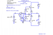
Whether it is specifically Hawksford-style ec I am not sure, this needs more study. In H-style ec there is a requirement that the ec loop has exactly a gain of 1. I guess your Q1 and Q3 should be seen as ec transistors? Then the input to the correction loop is at their emitters and the reference from Vin at their bases. The output current from the collector is through R2, R5 and generates the correction to Vi (Vi here is, I guess, the junction of R6, R2. Am I still on track?
Then the 64000$ question becomes: does a 1V error between B and E lead to an exactly 1V correction at the R2, R6 junction?
Jan Didden
PMA said:If I came with my (and NP's) 12 cents, would you call this feedback, error correction or both?
It certainly is 'a' form of error correction, as all forms of feedback, feedforward etc are a form of error correction.
Whether it is specifically Hawksford-style ec I am not sure, this needs more study. In H-style ec there is a requirement that the ec loop has exactly a gain of 1. I guess your Q1 and Q3 should be seen as ec transistors? Then the input to the correction loop is at their emitters and the reference from Vin at their bases. The output current from the collector is through R2, R5 and generates the correction to Vi (Vi here is, I guess, the junction of R6, R2. Am I still on track?
Then the 64000$ question becomes: does a 1V error between B and E lead to an exactly 1V correction at the R2, R6 junction?
Jan Didden
Life has taught me:
If you love, love without reservation.
If you fight, fight without fear.
DIYaudio has taught me:
If you love using global feedback, use a lot without reservation.
If you fight using global feedback, use none without fear.
Bob,
Thank you for putting in the time to design a 3-level emitter follower output with Hawksford error correction and presenting distortion data showing that "its a good thing".
It now seems key to also design no-global feedback input and VAS stages to marry with your 3T bipolar error correction output. This would tie together several of your threads.
Will zero global feedback reduce the higher odd harmonics? What does it sound like?
janneman said:
Hi David,
I haven't tested it rigourously yet, but what I see on the scope seems more or less what I would expect in a feedback amp. I have the *impression* it isn't much different.
I am currently looking at putting reverse-parallel diodes across the input resistor (the one that effects the EC) so that when overdriven, the EC cannot grow higher. Problem here is that it starts to influence the THD behaviour already before overdrive.
Jan Didden
Although the schematic is obsolete and I haven’t updated it yet (been redesigned with 30 pairs of much higher fT MJE15028[9] devices and a peak I limit of 100A), my EC scheme here:
http://users.picknowl.com.au/~glenk/CLASSA.HTM
.....shows how I solved the problem of the EC fighting the current limit. The current limit transistors (Q32 and Q33) simply clamp the error voltage developed between the output and the output stage side of the input resistor R1 (R25 in your schematic). This method is simple and works really well.
Cheers,
Glen
LineSource said:Life has taught me:
If you love, love without reservation.
If you fight, fight without fear.
DIYaudio has taught me:
If you love using global feedback, use a lot without reservation.
If you fight using global feedback, use none without fear.
Bob,
Thank you for putting in the time to design a 3-level emitter follower output with Hawksford error correction and presenting distortion data showing that "its a good thing".
It now seems key to also design no-global feedback input and VAS stages to marry with your 3T bipolar error correction output. This would tie together several of your threads.
Will zero global feedback reduce the higher odd harmonics? What does it sound like?
Hi LineSource,
Thanks, but if you are referring to what I posted above, it wasn't a BJT T output stage with error correction. It was just a SPICE simulation of an error-corrected output stage using real devices as the final output stage, but ideal SPICE elements as the rest of it. The schematic is posted here.
Although a fine amplifier without global NFB could be made with a BJT T output stage with error correction, I don't think it would go over so well with the no-feedback afficiondos, since the EC can be viewed as a form of NFB, albeit fast and tight.
Zero global feedback will almost never reduce higher-order odd harmonics in comparison to what they would have been without NFB.
Cheers,
Bob
Attachments
janneman said:Hi Glen,
Thanks for that, it surely is an elegant way to solve it! I'll see how this would work in my implementation.
No worries
Are you using overall nfb enclosing the output stage?
Yes I am. This is what will be driving it (when I finish loading the PCB):
http://users.picknowl.com.au/~glenk/MAIN.HTM
Cheers,
Glen
Now here’s an idea – why not design an amp with EC applied around the entire thing instead of conventional global NFB?
Instead of designing the amp with heaps of low frequency open loop gain and then rolling it off with distortion causing frequency compensation, design the amp as though you were making a zero-GNFB amplifier, with a flat, uncompensated open loop gain – say +26dB.
Then apply frequency compensated EC around the whole thing - just tweak the EC circuit gains to compensate for the forward gain of +26dB.
Cheers,
Glen
G.Kleinschmidt said:
Interesting variation of EC there Glen!
G.Kleinschmidt said:Now here’s an idea – why not design an amp with EC applied around the entire thing instead of conventional global NFB?
Instead of designing the amp with heaps of low frequency open loop gain and then rolling it off with distortion causing frequency compensation, design the amp as though you were making a zero-GNFB amplifier, with a flat, uncompensated open loop gain – say +26dB.
I think that's what Jan is doing, and I believe Rodolfo (ingrast) is doing that also. Last I heard Rodolfo was working on an AES article on the subject, but I don't know if it's been approved yet.
andy_c said:
I think that's what Jan is doing, and I believe Rodolfo (ingrast) is doing that also. Last I heard Rodolfo was working on an AES article on the subject, but I don't know if it's been approved yet.
OK, cool, thanks Andy.
I actually got the idea from looking at Jan's unity gain EC output stage experiment shown in post 2001:
http://www.diyaudio.com/forums/showthread.php?postid=1273756#post1273756
Though I haven't really given this idea much thought, it does sound feasible.
Cheers,
Glen
- Home
- Amplifiers
- Solid State
- Bob Cordell Interview: Error Correction