That's a good point ! I notice in the schematics a 1R0 and 220 nF. Should I be replacing the 1K2 with these components ?
Is 1R0 equal to 10 ohms or 1 ohms ? Is the capacitor an electrolyte with polarity ?
The previous owner told me that an audio shop changed the speaker terminals, so they most likely did not replace with the right resistors.

Is 1R0 equal to 10 ohms or 1 ohms ? Is the capacitor an electrolyte with polarity ?
The previous owner told me that an audio shop changed the speaker terminals, so they most likely did not replace with the right resistors.
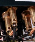
leave those in place - they're Boucherot filter , most probably crucial for amp's stability ;
those 1K2 resistors across speaker terminals - replace themwith 150R-220R
edit: that 1R (R is EU for Ohm) and 220nF (nonpolarized , you can see that from symbol ) are most probably on pcb , being connected pre-switch
those 1K2 resistors across speaker terminals - replace themwith 150R-220R
edit: that 1R (R is EU for Ohm) and 220nF (nonpolarized , you can see that from symbol ) are most probably on pcb , being connected pre-switch
Attachments
Last edited:
The output is AC coupled. It needs to be because there is half supply voltage between the speaker and the amp output.
The 10mF cap needs to charge up to half voltage, without the speaker connected at power ON.
The same cap needs to discharge at Power OFF without the speaker connected.
Similarly the headphones must not be connected suring power ON or OFF.
A relay to delay the speakers and headphones while connecting a temporary charging/discharging resistor, should be fitted.
Did Sugden not fit a relay as standard? Or have they described an ON/OFF procedure in the manual, using the headphones resistors but without the headphones connected?
The output is AC coupled. It needs to be because there is half supply voltage between the speaker and the amp output.
The 10mF cap needs to charge up to half voltage, without the speaker connected at power ON.
The same cap needs to discharge at Power OFF without the speaker connected.
Similarly the headphones must not be connected suring power ON or OFF.
A relay to delay the speakers and headphones while connecting a temporary charging/discharging resistor, should be fitted.
Did Sugden not fit a relay as standard? Or have they described an ON/OFF procedure in the manual, using the headphones resistors but without the headphones connected?
I do not see any power on / off procedure in manual to protect speakers ... I guess I will need some type of relay design that will work on this amp to protect speakers. Any suggestions ?
Hum noise
Here's what the buzz noise sounds like.
I recorded it here: http://www.trilliumproductions.ca/buzz.wav
UPDATE: I just noticed that the buzz only happens with the AUX input. If I use the CD input there's no BUZZ.
Here's what the buzz noise sounds like.
I recorded it here: http://www.trilliumproductions.ca/buzz.wav
UPDATE: I just noticed that the buzz only happens with the AUX input. If I use the CD input there's no BUZZ.
Last edited:
Here's what the buzz noise sounds like.
I recorded it here: http://www.trilliumproductions.ca/buzz.wav
UPDATE: I just noticed that the buzz only happens with the AUX input. If I use the CD input there's no BUZZ.
I isolated the problem as being the AUX connectors floating from the chassis ground. Fixed that in a hurray. All is well now.
Hi Michael, I own 2 P28s with heatsinks at the back. Can you spare a copy of the schematics for me at iamjj11@me.com? I also have the C28 preamplifier but no schematicz. Can anyone else help? Thank you from a novice Sugden owner.Bonjour Philippe,
Are the heat sinks on each side or at the back of the amplifier ?
Send me your email address so I can send the schematics.
Salutations,
Michel
A28 volume control knob freewheels on shaft
I've had a scratchy pot in my A28 and took Michel's advice above. I had to remove the ALPS pot because it was soldered to the board. There was extreme difficulty removing to knob but I was able to lever the knob off without doing any damage. I assumed the fit was an interference fit and age had effectively 'glued' the parts together.
However, after putting the pot back the knob is now a free fit on the shaft and with the short shaft there is no way I can use a different knob with a screw to hold it in position. Does anyone have a solution to this problem that I can try?
(Edited)
You probably do not need to replace the volume potentiometer as a cleaning usually corrects the problem.
For this cleaning to be effective you need to use a quality product like DeoxIT®, #D5S-6 from Caig.
If your potentiometer is an Alps Black Velvet you need to lift the film pressed over the connections to be able to reach the slots and gain access.
If it is soldered to the main pcb I think you will have to unsolder it to be able to clean it.
Michel
I've had a scratchy pot in my A28 and took Michel's advice above. I had to remove the ALPS pot because it was soldered to the board. There was extreme difficulty removing to knob but I was able to lever the knob off without doing any damage. I assumed the fit was an interference fit and age had effectively 'glued' the parts together.
However, after putting the pot back the knob is now a free fit on the shaft and with the short shaft there is no way I can use a different knob with a screw to hold it in position. Does anyone have a solution to this problem that I can try?
A28 bias voltage dropping over time
Just checked the bias current on the A28 after an extensive warm up and it's dropped below 200mA on both channels from the nominal 300mA I set it at two and a half years ago. Is this normal?
Thanks Andrew. I'll try that first.A gap filling adhesive might take up the excess clearance.
Just checked the bias current on the A28 after an extensive warm up and it's dropped below 200mA on both channels from the nominal 300mA I set it at two and a half years ago. Is this normal?
Bonjour Philippe,
Are the heat sinks on each side or at the back of the amplifier ?
Send me your email address so I can send the schematics.
Salutations,
Michel
Hi Michel! I read this and maybe you can help me coz I need the Sugden P28 schematics real bad. Something went wrong with my amp and my tech needs to work on it. My email address is jborama@gmail.com. I will appreciate it very much! Thanks!
Hi Michael,
I am about to get my hands on a Sugden P28 b , power amp with coolers on sides. Please be kind and send me a service manual if you have one. I have an intention of "refreshing" it and without original data there no sence starting... My e-mail is darko960@gmail.com
I will post pictures of it after I get in my hands.
rgds from Split, Croatia - Darko
Hi Michel, hi folks
I need the schematics for a Sugden A28 ( black unit, white lettering, heatsink on the back, not A28II or A28B )
Can anyone please send me the schematics/ service information?
email: rene.beutke@gmx.de
Best regards,
René
I need the schematics for a Sugden A28 ( black unit, white lettering, heatsink on the back, not A28II or A28B )
Can anyone please send me the schematics/ service information?
email: rene.beutke@gmx.de
Best regards,
René
Hi my name is Erik and since 2019 I own a Sugden A28 mk2 - black housing with gold panel lettering
Before the previous owner sold it, the amp had been checked. Some parts had been soldered and volume potentiometer was replaced by a blue Alps.
Yesterday I was listening and enjoying a "new" pair of KEF Reference 103.2 that i bought. After a couple of hours I had to go for a walk with the dog. Because the A28 gets quite warm, I turned it off for.
When I came back after an hour or so, the right channel no longer worked.
Just before I went walking with the dog, I thought the music started to sound a bit dull / soft / fuzzy. This might be an indication that there was something wrong?
On the inside the amp looks very nice and clean.
Right side of the amplifier does not get warm.
I found 4 fuses: 1 at the back-panel, 1 in the front of the print, and 2 in the middle of the print. They appear to be okay.
On the internet (mainly this forum) I found that:
So i have to bring the A28 for service somewhere.
1. Does anyone know a good address in The Netherlands for repairing these vintage models. Maybe a vintage specialized technician that really knows and loves these old machines? Specially Sugden.
2. And now that the amplifier is being checked/serviced: are there any additional things that have to de done? Certain parts checked or replaced in advance? Certain measurements? All recommendations are welcome.
Hope to hear from you.
Before the previous owner sold it, the amp had been checked. Some parts had been soldered and volume potentiometer was replaced by a blue Alps.
Yesterday I was listening and enjoying a "new" pair of KEF Reference 103.2 that i bought. After a couple of hours I had to go for a walk with the dog. Because the A28 gets quite warm, I turned it off for.
When I came back after an hour or so, the right channel no longer worked.
Just before I went walking with the dog, I thought the music started to sound a bit dull / soft / fuzzy. This might be an indication that there was something wrong?
On the inside the amp looks very nice and clean.
Right side of the amplifier does not get warm.
I found 4 fuses: 1 at the back-panel, 1 in the front of the print, and 2 in the middle of the print. They appear to be okay.
On the internet (mainly this forum) I found that:
- the balance control of this Sugden is sometimes the problem, that is dried out solder contacts.
- that "sounding fuzzy" is a sign for end of life of the output transistors
- that if you replace capacitors, replace them with a higher voltage rating and higher temperate (105 i.s.o. 85)
So i have to bring the A28 for service somewhere.
1. Does anyone know a good address in The Netherlands for repairing these vintage models. Maybe a vintage specialized technician that really knows and loves these old machines? Specially Sugden.
2. And now that the amplifier is being checked/serviced: are there any additional things that have to de done? Certain parts checked or replaced in advance? Certain measurements? All recommendations are welcome.
Hope to hear from you.
- Home
- Amplifiers
- Solid State
- Sugden P28