Some background. I was asked to repair this CA-1000 integrated after the current owner bought it pretty much in pieces, along with a pile full of blown output transistors. Not a good omen.  He did a decent job of putting Humpty Dumpty back together again, though it's hard to say if he introduced any new issues to those that apparently already existed. Among those issues, the owner found that R626 on the left amp board was a charred ruin. He replaced it with a new 330 ohm resistor.
When I got it on my bench, I found that a fusible resistor on the power supply board had drifted very high, drastically reducing the B+ to the left channel. All the outputs tested ok. After replaced the fusible, I was able to power it up and set the bias for both Class A/B and A (this has a switch to toggle between the two), set the DC offset, and dial in what the service manual calls the Primary Stage Differential Amplification to 15V. So far, so good. As a little preventive maintenance, I recapped the power supply (but not the two main filter caps), replaced the two bias trimmers on each board, and also replaced C603 and R607 on the two amp boards as there was some glue that had turned corrosive around the cap that also affected the resistors. Powered up, rechecked and tweaked bias, DC offset, and differential amplification. All good.
Until it wasn't. All went to hell when I went to test the amp with an 8 ohm load and R626 on the right board released the magic smoke. Very spectacular As a reminder, this is the same resistor that had combusted on the left board before the amp found its way to me. Whatever caused R626 to go this time on the right board also took out a number of other components, including the outputs.
Here's what was damaged and the replacements:
Right
A: -0.222 (-0.148) -0.28
B: -0.172 (-0.148) +1.15
C: -0.172 (-0.148) +1.15
S: +2.47 +3.9
-50: -50.6
+50: +50.0
-B: -49.3
+B: +49.3
It wasn't damaged by I also replaced TR606 (2SC458 with KSC1845) and the two micro switches for the Class A/B - A toggle, as my understanding is that these get damaged from arcing and can cause bias issues.
Earlier today, I powered up the amp again, this time with a 100W bulb in my DBT. TR606 no longer linked out. Bulb dimmed almost completely and the protection relay clicked. The left channel bias was low but steady, whereas the right channel bias fluctuated significantly, i.e. tens of millivolts. I didn't like what I was seeing, so I shut it down. The left channel bias voltage went to zero, but the right channel voltage did not. In fact, it starting rising to over 100mV before finally going to zero. I did a quick check of the components damaged last time, and everything seems ok, with one exception: R626 is now open.
Sorry for the long, epic post, but I figured more info is better than too little. Lacking any better ideas, I'm probably going to check every component on the right board. In the meantime, I could definitely use some input. What the hell is causing R626 to die on these boards and, left unchecked, kill outputs?
He did a decent job of putting Humpty Dumpty back together again, though it's hard to say if he introduced any new issues to those that apparently already existed. Among those issues, the owner found that R626 on the left amp board was a charred ruin. He replaced it with a new 330 ohm resistor. When I got it on my bench, I found that a fusible resistor on the power supply board had drifted very high, drastically reducing the B+ to the left channel. All the outputs tested ok. After replaced the fusible, I was able to power it up and set the bias for both Class A/B and A (this has a switch to toggle between the two), set the DC offset, and dial in what the service manual calls the Primary Stage Differential Amplification to 15V. So far, so good. As a little preventive maintenance, I recapped the power supply (but not the two main filter caps), replaced the two bias trimmers on each board, and also replaced C603 and R607 on the two amp boards as there was some glue that had turned corrosive around the cap that also affected the resistors. Powered up, rechecked and tweaked bias, DC offset, and differential amplification. All good.
Until it wasn't. All went to hell when I went to test the amp with an 8 ohm load and R626 on the right board released the magic smoke. Very spectacular
As a reminder, this is the same resistor that had combusted on the left board before the amp found its way to me. Whatever caused R626 to go this time on the right board also took out a number of other components, including the outputs. Here's what was damaged and the replacements:
- R626 (replaced with 1/4W 330 ohm)
- D602 (replaced with 1N4148)
- R628 (replaced with 1W 4.7 ohm)
- TR608 (2SA561 replaced with KSA1013Y)
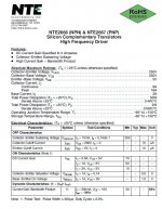
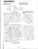
- TR610 (2SA566 replaced with NTE2667--note that TR609 is still the original 2SC680 driver)
- TR611 (replaced with NTE280)
- TR612 (replaced with NTE281)
Right
A: -0.222 (-0.148) -0.28
B: -0.172 (-0.148) +1.15
C: -0.172 (-0.148) +1.15
S: +2.47 +3.9
-50: -50.6
+50: +50.0
-B: -49.3
+B: +49.3
It wasn't damaged by I also replaced TR606 (2SC458 with KSC1845) and the two micro switches for the Class A/B - A toggle, as my understanding is that these get damaged from arcing and can cause bias issues.
Earlier today, I powered up the amp again, this time with a 100W bulb in my DBT. TR606 no longer linked out. Bulb dimmed almost completely and the protection relay clicked. The left channel bias was low but steady, whereas the right channel bias fluctuated significantly, i.e. tens of millivolts. I didn't like what I was seeing, so I shut it down. The left channel bias voltage went to zero, but the right channel voltage did not. In fact, it starting rising to over 100mV before finally going to zero. I did a quick check of the components damaged last time, and everything seems ok, with one exception: R626 is now open.
Sorry for the long, epic post, but I figured more info is better than too little. Lacking any better ideas, I'm probably going to check every component on the right board. In the meantime, I could definitely use some input. What the hell is causing R626 to die on these boards and, left unchecked, kill outputs?
Attachments
Could be intermittent connection somewhere.
Bias is fluctuating from poor connection.
Looks like the way the bias control pot is setup
if connection is lost it would bias hard full on.
I see external connections on that schematic to another board.
Guessing that is the " bias" control switches etc etc.
could be intermittent connections on the bias control board.
or whatever connectors or wires that make those external connections.
to the lettered connectors on the schematic
A, B , S , C
just a guess of course, but its rather stupid how they made that bias circuit.
it would nail the living heck out of the output if connection is lost.
R616 should help if the pot lost connection
but it leads out to B so still possible to cause a full bias on
if connection is lost on whatever that external board does.
I know where this thread is coming from...
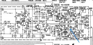
For R626 to burn you must be seeing a situation that causes either the 0.47 ohm, the PNP output B-E junction or the 4.7 ohm base stopper resistor to go open or high resistance. All those three are effectively in series and across the 330 ohm and will clamp the voltage across that resistor to very low levels.
So there must be something going open or high out of those three or a broken trace somewhere on those.
Would a bias fault severely overloading the output stage cause that?
Its not a normal scenario, typically the output device would fail short and hopefully blow a rail fuse.
It is possible the 0.47 ohm could be faulty and goes high in value when significant but normal current flows. Same I suppose for the 4.7 ohm.
If the fault persists with the bias generator shorted then we know for sure that anything related to the bias side of things can be ruled out.
I still think you have to get it to that point and run it normally with a load to confirm it is good.
Then look at the bias.
Correction (a major one): R626 is NOT blown again. I checked it a few times last night on the component side of the board, and I swear it was measuring open. Now I checked again on the solder side, and it's fine. So putting aside the original issue with R626 for the moment, I need to figure out what caused what I saw with the bias fluctuating all over the place the last time I powered up the amp.
One key component that I changed after the initial damage was the driver TR610. The original 2SA566 is in the obsolete TO-66 package, so I needed to sub in a TO-220 package. Having read that people have replaced 2SA566 with an MJE15033G, I used the equivalent NTE 2667. (Not ideal, but it was handy.)
Another component I changed was TR606, swapping out the original 2SC458 for a KSC1845. (Yes, I should have left TR606 alone, since it was ok.)
- Could the NTE 2667 at TR610 cause the crazy bias readings? Or the fact that I didn't replace its complement TR609 with an NTE 2666, and instead left in the original 2SC680?
- Could the sub of a KSC1845 at TR606 be at fault?
Attachments
This was the most recent time I had powered up the amp, which was after removing the short across the vbe multiplier. It was my test with the bias circuit back in action.
While measuring the voltage across the two 0.47 emitter resistors, I observed that the reading fluctuated wildly, going up to 60 or 70mV while powered on, and then reaching over 100mV even after shutting things down.
My first thought: What did I change, component-wise, that might be causing this problem?
pre-driver TR608
driver TR610
vbe multiplier TR606
It may be that none of these changes caused what I observed on my meter, but I figured I'd better rule them out first. See previous post about the specific subs used.
Does fluctuating wildly mean just in terms of value or does it mean altering up and down very rapidly as well? Rapid jumps in value should not be occurring.
Q606 should not be critical in any way as to the type fitted.
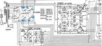
What goes on top left of the circuit where all those connections go may need investigating. Is it just a switch they all go to or is there more to it than that?
Q606 should not be critical in any way as to the type fitted.
What goes on top left of the circuit where all those connections go may need investigating. Is it just a switch they all go to or is there more to it than that?
I'd say it was rapid jumps in value.
Those connections all go to what Yamaha calls the operation switch for toggling between Class A and Class AB bias. It's what WhiteDragon is referring to in his post and consists of a central sliding switch and two micro switches. This is how it was explained to me in an offline exchange with someone who's worked on several CA-1000 amps:
I have already removed the board these switches are mounted on and checked the sliding switch with my meter. It measured .02 ohms across the contacts in each position, so I didn't disassemble it to try cleaning it.
Those connections all go to what Yamaha calls the operation switch for toggling between Class A and Class AB bias. It's what WhiteDragon is referring to in his post and consists of a central sliding switch and two micro switches. This is how it was explained to me in an offline exchange with someone who's worked on several CA-1000 amps:
A,B,C and S are not power supply pins as such, they are more about selecting and connecting the wanted VR for Class A and AB. In normal pins B&C are shorted togher, for Class A pins A&C&S are shorted. These pins are helpful since they provide easily accessible test points. Also, if the voltages for the shorted pins are not the same then need to clean the operations slide switch, next to the snap switches, the slide switch performs the shorting, the snap switch does the high voltage/B+ switching.
Sounds like I should measure low ohms between solder pads B & C on the amp board when the switch is in Normal (AB) mode, and between A, C, and S in Class A mode.
I have already removed the board these switches are mounted on and checked the sliding switch with my meter. It measured .02 ohms across the contacts in each position, so I didn't disassemble it to try cleaning it.
Attachments
Appears you are talking about power ON/Off transients, those numbers (mV) would not concern me (=transients). If these readings are obtained after the power on mute period (3-8? seconds) then I'd be concerned.While measuring the voltage across the two 0.47 emitter resistors, I observed that the reading fluctuated wildly, going up to 60 or 70mV while powered on, and then reaching over 100mV even after shutting things down.
.
No, not transients. I'm probably not describing it very well.
I powered up the amp and observed the two bench meters I had hooked up to bias test points 3 and 4 on both boards. After the protection relay clicked, I paid attention to the voltage readings on the right channel. I don't recall the exact numbers, but they were moving up and down fairly quickly, e.g. 20mV up to 40mV, then down, then up to 60mV or 70mV, then down. I didn't like what I was seeing, so I cut the power. Instead of seeing the voltage across the emitter resistors drop down, it actually started to steadily rise for several seconds after there was no power, reaching over 100mV. It was like the bias was running away, even though the mains power was disconnected.
I powered up the amp and observed the two bench meters I had hooked up to bias test points 3 and 4 on both boards. After the protection relay clicked, I paid attention to the voltage readings on the right channel. I don't recall the exact numbers, but they were moving up and down fairly quickly, e.g. 20mV up to 40mV, then down, then up to 60mV or 70mV, then down. I didn't like what I was seeing, so I cut the power. Instead of seeing the voltage across the emitter resistors drop down, it actually started to steadily rise for several seconds after there was no power, reaching over 100mV. It was like the bias was running away, even though the mains power was disconnected.
Part of the function of the protect circuit is to "mute" power ON/OFF transients so you don't get that annoying thump in the speakers. Generally not concerned about voltages after power off. Bias for AB is 47mV, maybe take 1-2 minutes after power on. "Dancing" around 60-70mV and then back to 40mV(?) is not normal and you need to track this down. Don't be overly concerned about 100mV since Class A bias is 940mV however watch carefully. Have you tried monitoring bias in Class A, stable. For AB the voltage rails are about +/-50V, for class A about +/-20Vdc at the outputs, maybe something breaking down under the higher volts?
Ok, good point about the 100mV being nothing to worry about. I forgot how high the Class A bias is set at. I'll likely power it up one more time and pay close attention to the activity of the right channel bias voltage and see if it acts as I recall.
Going back to a previous post of mine: How bad (if bad at all) is it that I have mismatched drivers at TR609 and TR610? To refresh, TR610 is an NTE 2667, which based on the datasheets is actually a relabeled MJE15033G. Its NPN complement, TR609, is still an original 2SC680.
Going back to a previous post of mine: How bad (if bad at all) is it that I have mismatched drivers at TR609 and TR610? To refresh, TR610 is an NTE 2667, which based on the datasheets is actually a relabeled MJE15033G. Its NPN complement, TR609, is still an original 2SC680.
I'd say it was rapid jumps in value.
I would say it should not be rapid. Slow drift happens but not jumping about.
Easy to prove if there is a problem with the switching by disconnecting A,B,C, and S at the transistor end fitting a temporary preset between collector and base of the vbe multiplier.
(Given that mechanical switches always in my experience go noisy and intermittent the design of that bias circuit seems... well lets say very poor indeed)
Easy to prove if there is a problem with the switching by disconnecting A,B,C, and S at the transistor end fitting a temporary preset between collector and base of the vbe multiplier.
Ok, when you say "temporary preset," do you mean wire a jumper?
Swap tr602 and 603 to the other channel
I can try that, but what's making you suggest this?
I can try that, but what's making you suggest this?
This pair sometimes cause small DC offset problems in my experience
Ok, when you say "temporary preset," do you mean wire a jumper?
No, I mean fit a preset pot so you can set the current and see if it is now stable.
- Home
- Amplifiers
- Solid State
- Yamaha CA-1000: Amp Board Issue