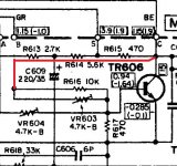
Ok. Not trying to be difficult (or dense 🙄), but if I want to test whether the switch is a problem, why not disconnect the wires for A, B, C and S at the amp board and jumper across the pads for B and C, i.e. which go to the collector and base of TR606?
If you jumper B and C you will just fully turn on the vbe multiplier which should give an identical result to how it was when you linked it out.
You need to set the bias to some test level and check it is stable and that means using a preset. Obviously begin with the preset at a near short to avoid to high an initial test current.
You need to set the bias to some test level and check it is stable and that means using a preset. Obviously begin with the preset at a near short to avoid to high an initial test current.
But flipping the operation switch to "Normal" bias connects the wires going to amp board terminals B and C via the sliding switch. If what we're talking about is confirming that there's no problem with the switch, we'd want to bypass the switch connection by removing the wires at terminals B and C and jumpering them at the board.
Attachments
You have to isolate the switch from the circuit first and just tag a preset between base and collector 🙂
Switch contact can certainly go intermittent. In AB pins B&C will be short. Connecting a jumper between B&C, leaving all other wires in place will take the switch out of play.if I want to test whether the switch is a problem, why not disconnect the wires for A, B, C and S at the amp board and jumper across the pads for B and C?
Expect VR603 and R616 still control TR606 with B&C jumpered?If you jumper B and C you will just fully turn on the vbe multiplier which should give an identical result to how it was when you linked it out.
Took a break from this, but now I'm back. 😉
I stubbornly decided to do it my way: I took the operation switch out of the circuit by unplugging the right channel wire harness (at the operation switch board) and then jumpering B and C on the amp board. It biased up fine. Then I plugged the harness back in and removed the jumper. Still no problem. So what changed from when I was seeing that weird fluctuating bias?
I swapped out the NTE 2667 that I had installed at TR610 with a KSA940 and TR609 with a KSC2073. I also used a different DMM on that channel that I had last time. I think, but don't know, that something was screwing up the mV range readings with that meter. Regardless, I'm now able to set the bias for both Class A/B and Class A modes. More testing still needed to see if whatever caused R626 to combust remains an issue. . . .
The only logical things that changed would be having an intermittent connection at the plug/socket you removed or having a bad connection elsewhere that the action of physically mauling the board while unplugging the connector temporarily healed up.
Sometimes and if you are not 100% sure then it can be best to make the suspect connections permanent (solder them) replace the presets and do the same for any plugs at the switch end of the board. That then just leaves the switch as a possible suspect. Clean it up and it should be good.
Sometimes and if you are not 100% sure then it can be best to make the suspect connections permanent (solder them) replace the presets and do the same for any plugs at the switch end of the board. That then just leaves the switch as a possible suspect. Clean it up and it should be good.
The amp itself just ruled out my possible explanations for the bias fluctuations (mismatched drivers and faulty DMM), as it acted up again. Paying close attention this time, I noticed a few things:
- The bias fluctuation was small at first, maybe up and down by 3 to 5mV. That's compared to how it was before and what I see in the other channel: very steady with fluctuations of only .1 to .3mV as the amp is warming up.
- After a minute or two, the fluctuations became larger, i.e. 10s of millivolts up and down, peaking at a little over 100mV again (not the swings, just the total reading).
- I shut the amp off, waiting a few minutes, and then powered it up again. No fluctuation/acting normally for about five minutes. Bias continued to climb in tandem with the left channel, as it should. Then it suddenly dropped from about 40mV to 6mV or so.
Last edited:
I've lost track what you've (positively) eliminated and what you haven't
Have you had a close look at the board(s) for drys ?
Is the problem limited to just one channel still/now?
Was that switch positively ironed out as good ?
If so, maybe it's worth going carefully through various resistor values to make sure it's not a dodgy resistor - at least you would have eliminated them.
A recap of what you've positively elimiated would be good and will obviously narrow down the search to the culprit, be it a semi or dry or drifty resistor (new word right there)
I have examined the solder joints on both boards, though I can certainly take another look.
Still just the right channel.
As for ruling out the switch, I've bypassed it again and am monitoring the bias as we speak. If the fluctuation happens again, then I'll have ruled out the switch. However, since this is an intermittent, I can't say the switch is ok if nothing happens.
I have checked all of the resistors on the board.
As for the switch , can you show a pic of it?, you described it earlier as a micro switch ?
It should have been able to 100% eliminate it miles ago.
Depending on the style/make of switch you may be able to push it into misbehaving by interfering with it physically (but gently) once re-enabled
It should have been able to 100% eliminate it miles ago.
Depending on the style/make of switch you may be able to push it into misbehaving by interfering with it physically (but gently) once re-enabled
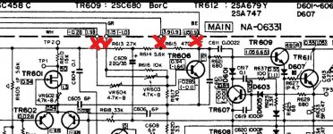
It's a sliding switch that connects and disconnects parts of the bias circuit in each channel and at the same opens and closes two micro switches that go to transformer secondaries. I replaced the micro switches. I desoldered the sliding switch itself and ohmed out the terminals, with each measuring 0.2 ohms.
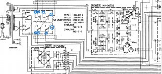
The whole thing is the "Operation Switch" in the schematic snippet.
The whole thing is the "Operation Switch" in the schematic snippet.
Attachments

Yeah I saw that - just thought I'd recognise it visually too
Although the rail switching element is important the other contacts are more importanter 😀
Check the legs (between body and pcb if you can see them) for signs of blackening/tarnishing to see if it a candidate for being totally at fault as intermittent contact with low current passing over the contacts.

The microswitches will be badly tarnished, you can get various operating force versions, although it won't make much difference to the feel. The stronger operating force versions do have a better contact though.
From expereince after seeing the pic the main switch contacts will be knackered too, I'd always try and overide with relays rather than try and clean them up on an important switching circuit like this ,.... you'll end up with a way better, more rerliable switch.... and you'll take all the streian off that ageing switch by doing all the switching with nice shiny relay contacts.
From expereince after seeing the pic the main switch contacts will be knackered too, I'd always try and overide with relays rather than try and clean them up on an important switching circuit like this ,.... you'll end up with a way better, more rerliable switch.... and you'll take all the streian off that ageing switch by doing all the switching with nice shiny relay contacts.
Checked the new snap switches I had installed (photo shown by mbz isn't of mine). The metal bar that depresses one of the pins did have a slight bend to it, which after straightening pushed the pin in a little further. Kinda doubt that was the issue, but at this point I'm running out of ideas. . . .
I'll reflow any suspect solder joints on the amp board, and then pull the slide switch from the operations board, disassemble, clean, and reinstall it.
Fwiw I monitored the bias in both channels for at least two hours this afternoon, and not once during that time did the right channel act up. Tried tapping all over the amp board, but nothing. Also tried tapping the operation switch and the board. Nada.
I reflowed a number of solder joints on the amp board, including those for the S, A, B, and C connections. I then disassembled and cleaned the operation sliding switch. After that, I was able to log about 8 hours without any bias fluctuations in the right channel. Even listened to music for a bit.
Then I checked both channels again in Class A mode. After about 10 minutes, I saw the bias fluctuation occur in the left channel. The bias had been set at 920mV, and it would drop down to as low as 650mV, come back, drop down again to some point in between, rise back up to around 920mV, etc. It never went over 920mV. The right channel was stable the entire time.
I'm going to resolder the S, A, B, and C connections on the left board next.
- Home
- Amplifiers
- Solid State
- Yamaha CA-1000: Amp Board Issue