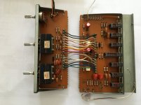
C and D boards
C board and D boards
These come as a pair by virtue of all the wire wrapping linking them together
The C board is tone control, nothing in here needs touching really, just the standard scrub and so on
The D Board – marked as control in the service manual
C210, C260 – 10uF / 25v replaced with 4.7uF / 63v film
C209 C259 – 470uF / 6.3v (New type) replaced with 470uF /16v poly
And clean the switches out of course
Without thinking I initially elected not to replace RV202/252 but, as I'm writing this, I think that's actually still standard enough to be replaced. It's also the balance pot so pretty important
Andy
Attachments
A short interlude now follows as a matching TC-K7ii arrived with only one VU meter lit :-0 and that will NOT do.
Elevator Music & Elevator Jazz: 3 HOURS of Jazzy Elevator Music and Elevator Jazz Music - YouTube
side note: wooden cheeks make hi-fi appear slimmer, not sure how that works, some industrial designer somewhere has the answer.
Next for the TA 4650 is reattach all the power stuff and then "do the full clench" with power on. No Vfets fitted except in the Phono stage of course. I really hate that part with these amps - it's a very first world stress")
Andy
Elevator Music & Elevator Jazz: 3 HOURS of Jazzy Elevator Music and Elevator Jazz Music - YouTube
side note: wooden cheeks make hi-fi appear slimmer, not sure how that works, some industrial designer somewhere has the answer.
Next for the TA 4650 is reattach all the power stuff and then "do the full clench" with power on. No Vfets fitted except in the Phono stage of course. I really hate that part with these amps - it's a very first world stress
Andy
A short interlude now follows as a matching TC-K7ii arrived with only one VU meter lit :-0 and that will NOT do.
Elevator Music & Elevator Jazz: 3 HOURS of Jazzy Elevator Music and Elevator Jazz Music - YouTube
side note: wooden cheeks make hi-fi appear slimmer, not sure how that works, some industrial designer somewhere has the answer.
Next for the TA 4650 is reattach all the power stuff and then "do the full clench" with power on. No Vfets fitted except in the Phono stage of course. I really hate that part with these amps - it's a very first world stress
Andy
What’s the worst that can happen ?
Just measure the voltages on the vfet connectors to make sure they are roughly correct. Set the power board VR to give you 20V and set the bias as per service manual and then hope for the best. Dim bulb to the ready!
Good luck, break a leg or whatever the audio electronics equivalent is..
I do not connect V-FETs after such refurbishment. First check all voltages on the V-FET connection locations. I also used Series Resistor 25 - 50 Ohm to Drain connection for limiting current when you power the unit with VFETs- some one used lamps - check Posts on V-FET restoration - audiokarma posts
once you get correct bias voltage/ current Draw remove the resistors. First time I started with 50 Ohm and then replaced with 25 Ohm / then 10 ohm etc as V-FETS are precious
once you get correct bias voltage/ current Draw remove the resistors. First time I started with 50 Ohm and then replaced with 25 Ohm / then 10 ohm etc as V-FETS are precious
Gotcha
Somewhere there is a *really* good "do this then do that" guide to starting a Vfet amp. I've used it before but it now seems lost in the mists of time.
Basically it detailed the correct steps for checking & setting bias before you put the Power Vfets in IIRC the article also had voltages for specific points on the board.
Any pointers?
It will be at least a week before I pick this up. Apart from work, a couple of mechanical issues have cropped up.
#1 The 5mm stand off on the power board is not actually M3 - so that doesn't actually fit
#2 The new speaker posts need to be fitted before the PS board, I should have spotted this as I was very aware my go to amp posts didn't fit because "depth"
Thanks for the support all
Andy
Hi Andy,
I used this one for the 5650.
Sony TA-5650 restoration doc- It breaths life at last!
Also , the front and rear panels will hinge down. Undo the bottom screws and slacken the side and they will pivot.
Jon
I used this one for the 5650.
Sony TA-5650 restoration doc- It breaths life at last!
Also , the front and rear panels will hinge down. Undo the bottom screws and slacken the side and they will pivot.
Jon
Last edited:
Thanks
Cheers Jon I saw that, think the salient point was; to quote:
"Note when adjusting the bias trimmers you should see a range of adjustment of approximately 8-28v. You want to set for the highest voltage possible. Higher voltage= lowest bias setting."
It's not quite how my rose tinted glasses recall the thread I'm looking for, but the point (thanks Music2) is set the VR so that the bias is highest.
It's going back together now and I might actually *not* be working this weekend Optimistically, it would be nice to clear the kitchen table!
Andy
Sony TA-5650 restoration doc- It breaths life at last!
Also , the front and rear panels will hinge down. Undo the bottom screws and slacken the side and they will pivot.
Jon
Cheers Jon I saw that, think the salient point was; to quote:
"Note when adjusting the bias trimmers you should see a range of adjustment of approximately 8-28v. You want to set for the highest voltage possible. Higher voltage= lowest bias setting."
It's not quite how my rose tinted glasses recall the thread I'm looking for, but the point (thanks Music2) is set the VR so that the bias is highest.
It's going back together now and I might actually *not* be working this weekend
Optimistically, it would be nice to clear the kitchen table!Andy
20 V
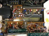
Ok so lets hope this isn't a false summit.
The amp is back together and power has been added to trim the 20V line
20.02v - Best I can do - it's also steady
Taking a breath: The voltages across the still Vfet-less Vfet pins are symmetrical to within a volt.
So, when everything is going well; step back and consider what you have missed...
For example at first turn on there was *nothing* no power light no response at all, no voltages where I was expecting - nothing. Turns out I had a power side air gap.
Andy
Ok so lets hope this isn't a false summit.
The amp is back together and power has been added to trim the 20V line
20.02v - Best I can do
- it's also steady Taking a breath: The voltages across the still Vfet-less Vfet pins are symmetrical to within a volt.
So, when everything is going well; step back and consider what you have missed...
For example at first turn on there was *nothing* no power light no response at all, no voltages where I was expecting - nothing. Turns out I had a power side air gap.
Andy
Attachments
So near - or so far
Hmm,
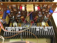
So after a busy few weeks I've finally got back to this; power on and checking voltages on the F-board one final time. Good swing from the Bias VR's and so on (see photo for voltages) Everything is super steady too
So at this point I linked the Pre-amp section back to the power - May have missed the part where I hooked that up to another power amp to check all was rosy. I did, It was.
Now here's the stumper: gate voltages drop from the 67 volt range to the 40 volt range.... Supply is still steady at 46.3v but you'll see the problem: Bias would be reversed and that's bad times
So the Vfets remain OUT for the moment.
My hope is it's just a Vfet-less anomaly. Both Channels behaving exactly the same should give me some comfort. I'm just sort of baffled that the pre-amp has an effect on the power amp voltages. They're separated by a cap after all. (I'm using the original links so no additional ground connection)
Thoughts / comments anyone, Should I be checking anything else? I'll accept that the Sony team probably didn't expect anyone to be prodding around 30 odd years later with the main components missing.
Andy
Hmm,
So after a busy few weeks I've finally got back to this; power on and checking voltages on the F-board one final time. Good swing from the Bias VR's and so on (see photo for voltages) Everything is super steady too
So at this point I linked the Pre-amp section back to the power - May have missed the part where I hooked that up to another power amp to check all was rosy. I did, It was.
Now here's the stumper: gate voltages drop from the 67 volt range to the 40 volt range.... Supply is still steady at 46.3v but you'll see the problem: Bias would be reversed and that's bad times
So the Vfets remain OUT for the moment.
My hope is it's just a Vfet-less anomaly.
Both Channels behaving exactly the same should give me some comfort. I'm just sort of baffled that the pre-amp has an effect on the power amp voltages. They're separated by a cap after all. (I'm using the original links so no additional ground connection)Thoughts / comments anyone, Should I be checking anything else? I'll accept that the Sony team probably didn't expect anyone to be prodding around 30 odd years later with the main components missing.
Andy
Attachments
Its all relative...
@jonboylaw
Yes that, I should have mentioned, "all voltages are relative to speaker ground"
There is a note in the thread you shared about this sort of thing too.
I'm looking at the schematic now, am I too far off to suggest that if Q308 conducts at all, the gate voltage for Q311 tends to zero (assume without the Vfets) because of the potential divider R319 and R320? So any noise and you'd see what I'm seeing? I'm not in any way experienced with transistor circuits so this might be politely [BUNK]
I didn't do this last check previously because the amp was known working prior, (perhaps ignorance is bliss) so I might be over thinking this
Andy
Attachments
So apparently I deleted my own reply #skillz
Yes, inputs grounded and using the aux input (one of them)
I am seeing about <5mv noise at the pre-out socket (I broke out the scope) but as far as the pre-amp is concerned that's a constant in that configuration
Power amp side is also playing as expected, no link to the pre = less noise (<5mv) I can of course see the PSU ripple at this level but "meh". Add the link to the Pre-amp and the noise increases but only a little maybe 2x. IMO to be expected more parts = more gain and noise.
Looks like a duck, walks like a duck....
Yes, inputs grounded and using the aux input (one of them)
I am seeing about <5mv noise at the pre-out socket (I broke out the scope
) but as far as the pre-amp is concerned that's a constant in that configuration Power amp side is also playing as expected, no link to the pre = less noise (<5mv) I can of course see the PSU ripple at this level but "meh". Add the link to the Pre-amp and the noise increases but only a little maybe 2x. IMO to be expected more parts = more gain and noise.
Looks like a duck, walks like a duck....
Fiddlesticks
SOooo
#1 Turns out that yes; putting the V-fets in stabilised the voltages nicely.
With/without the pre-amp linked in, the voltages measure as the previous picture.
#2 (AAaaand here's where the afternoon could have been better) Right channel setting bias nothing much happening, as usual with the multi turn pots, but I smell "warmth"... power off!! Too late = One dead V-fet pair
I'm a *little* annoyed as with hindsight I knew the 2SK60 was a survivor, I'm also sure it measured OK beforehand and gate and source voltages checked out so either it didn't like the stress or, more likely, I goofed somewhere.
Whatever, replacing the 2SK60 with a spare brought the voltages back there. But gate for the 2SK18 was now stuck at essentially zero volts. A further diode check confirmed it's fate along with it's sibling. [Insert flowery Anglo-Saxon here]
One other thing was that the right channel wasn't linked to the pre-when I was fiddling. To be fair I didn't think the left one was either but turns out i have a rogue link.
Left channel works fine. I've hooked up speakers and so on. It's a little bright (on the left ear) compared to the TA-5650, but loads of detail. In the fullness of time the aforementioned changes around caps in the signal path might need to be reviewed...
Anyone got a 55 rank 2SJ18??
Attachments

Having reviewed this afternoons events I'm putting it down to stupid on my part. Without the pre involved i think bias might have been a bit more ON than I expected. I've cooked 'em by over/under biasing.
no excuses, I do think this one's squarely at my feet
Seems to imply though, that it's worth checking the bias if anyone chooses to use these as a power amp, if only out of an excess of caution.
Tomorrows job is put the left channel Vfets in the right channel (carefully) If I'm sitting on a fully restored amp less 1/2 the Vfets then at least I know what shopping looks like...
- Home
- Amplifiers
- Solid State
- Another Sony TA 4650 V-fet thread