Well done
Ha! Well I missed that one.
All I see are ones from Japan or the US with their respective postage and import duties, so realistically a no go. I did notice some super brave person picked up an TA-8650 a couple of days ago.
I'll keep my eye out, but once the 'bench' is cleared of cassette deck, I have a TA-5650 to go through. It was working but untouched when I got it, I already swapped the diodes out but got distracted by the subject of this thread.
Hope it's 'as expected' when it arrives.
Andy
Hi,
For what it's worth, and contrary to the best advice, I use a 4 X100W light bulbs in series with power cord of my TA-5650: 2 light bulbs ON for first check out of right voltages and low volume sound test; then, when everything seems OK, I connect 3rd and 4rth bulbs, to complete biasing and for enjoying music.
When some error is there on initial powering on, the current consumption increases, the light glows 😱, the voltages collapses (yes, even the Gate Vs) and.. the main current-limiting protection circuit and the speaker protection kick-in 😱 It has, fortunatelly, never ceased to do so...😀
I will take the liberty to re-post here some excellent advices from dear Ilimzn adressing oscillation tendency from TA-5650, but which may apply in this case also:
Good luck,
M.
For what it's worth, and contrary to the best advice, I use a 4 X100W light bulbs in series with power cord of my TA-5650: 2 light bulbs ON for first check out of right voltages and low volume sound test; then, when everything seems OK, I connect 3rd and 4rth bulbs, to complete biasing and for enjoying music.
When some error is there on initial powering on, the current consumption increases, the light glows 😱, the voltages collapses (yes, even the Gate Vs) and.. the main current-limiting protection circuit and the speaker protection kick-in 😱 It has, fortunatelly, never ceased to do so...😀
I will take the liberty to re-post here some excellent advices from dear Ilimzn adressing oscillation tendency from TA-5650, but which may apply in this case also:
1) signal ground is routed all around the amp and any contact problems between the input connector and local ground will drive the amp crazy as it's entire input stage loses ground (reference). There are two nearby points on the PCB where the input ground and power ground are oposed with about 2cm of space, a 4.7 ohm resistor in parallel with 100pF cap should be mounted there. Also, local decoupling of the main power rails (44V) is recommended.
2) The driver transistors degrade, and they are not complementary. Replacement with something like 2SB649/2SD669 will work (even MJE340/350 if you really must!) but the small capacitances in the driver stages must be slightly increased (TA-5650=C310,313; TA-4650= C308-C309) to around 18-22pF.
Good luck,
M.
Last edited:
I did see that TA-8650, but would really need to see it in the flesh and test the V-FETs. I spoke to another chap that was selling an 8650, but it had mismatched V-FETs in it so he decided to try and get some matching ones to replace them.. With this one, I plan to do back to back testing vs my TA-5650 to see which sounds the best, single pairs or dual pairs.
Now I need to sell some Quad-405s I have lying around and then finish my SissySIT R3 before the misses notices..
Now I need to sell some Quad-405s I have lying around and then finish my SissySIT R3 before the misses notices..
Well we're right on the same page there! Curiosity killed the cat though 😀With this one, I plan to do back to back testing vs my TA-5650 to see which sounds the best, single pairs or dual pairs.
Andy
Hi,
For what it's worth, and contrary to the best advice, I use a 4 X100W light bulbs in series with power cord of my TA-5650: 2 light bulbs ON for first check out of right voltages and low volume sound test; then, when everything seems OK, I connect 3rd and 4rth bulbs, to complete biasing and for enjoying music.
When some error is there on initial powering on, the current consumption increases, the light glows 😱, the voltages collapses (yes, even the Gate Vs) and.. the main current-limiting protection circuit and the speaker protection kick-in 😱 It has, fortunatelly, never ceased to do so...😀
M.
I'm not 100% sure I follow that, are you putting bulbs in the supply 'cord'?
Can you hijack your own thread?
Unrelated post
Just to underline the joy of vintage hi-fi..
This might be poor etiquette as it's not about the original topic so much. Please forgive me.
However, "the bench is now clear" 🙂
Andy
Lots of info on the TA-5650 but I suppose 'IF' I choose to write up my meandering experiences there, it does warrant a separate thread, if only so folks can find it.
Clean the ($&*$) Volume Pot would be my first words of wisdom!!!
Attachments
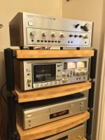
Check you with the fancy wooden sides…
Looks smart, right enough.
I think Max was stating that he used the 4 bulbs in series in the power lead to limit current if anything should go wrong. I use a 100w bulb in my power lead when setting the bias etc as it gives a litre warning if things are getting a bit spicy.
Jon
Looks smart, right enough.
I think Max was stating that he used the 4 bulbs in series in the power lead to limit current if anything should go wrong. I use a 100w bulb in my power lead when setting the bias etc as it gives a litre warning if things are getting a bit spicy.
Jon
Yes Jon, "nomenklatur" is potentially confusing...
I believe 100W is too little and risky in this case, especially if gate voltage does not rise fast enough or lowers too much during operation...200W is a minimum IMHO. Luckily, I've never lost any component, passive nor active.
I believe 100W is too little and risky in this case, especially if gate voltage does not rise fast enough or lowers too much during operation...200W is a minimum IMHO. Luckily, I've never lost any component, passive nor active.
Wait,
So as a precaution a couple of 100 watt bulbs (in parallel?) before the amp
Wish I known that a week ago. 😀
Andy
So as a precaution a couple of 100 watt bulbs (in parallel?) before the amp
Wish I known that a week ago. 😀
Andy
Hmm...
So to add to a previous realisation regarding the TA5650 there are some updates that occurred later in the TA5650 life cycle around the Pre-amp stage.
Just to follow up my previous post: Complimentary ramblings AKA another Sony TA-5650 V-Fet thread,
since I have service manuals for both 5650 and 4650 in front of me now;
for the TA4650 then:
C101 / C151 are marked as 3.3uf /25v in my service manual - equivalent component for a later TA5650 is 10u at 100v (I fitted 3.3/63v PET 🙁 )
C107 / C157 are marked as 470uf /10v these turned into a 35V part in later TA5650's (I upped this to a 25v part so at least moved in the right direction.)
Similarly C203 and C253 were upgraded from 10u/25v to 10u/100v
yes there's a pattern here...
The SM I have for the TA4650 does show later models on the power amp side, but only one version of the truth for everything else. I guess that these 'mods' didn't carry through for the baby amp? Or maybe it's the other way around 🙄
Anyway if I ever find myself in a position to use the amp, it'll warrant re-visiting. Esp C203 & C253 loads of space there 🙂
Andy
OOh we're back
Interim TA-5650 project not withstanding - more transistors sourced
These were from what otherwise looks water damaged 😱 but they do apparently work and measure OK
So Part two? Would like to finish the TA-5650 first but yes, looks like I can atone for my V-fet sins. But with less and more 😀
Andy
P.S. With an eye on the future if anyone viewing this thread can point me at the "Making the 2106 Vfet kit work with a 2SK60 and 2SJ18" page I'd appreciate it. There's THOUSANDS of pages of stuff between me and that answer. I mean I'll keep trawling, but it'd be a lot cooler if I could just get the info 😀
Interim TA-5650 project not withstanding - more transistors sourced
These were from what otherwise looks water damaged 😱 but they do apparently work and measure OK
So Part two? Would like to finish the TA-5650 first but yes, looks like I can atone for my V-fet sins. But with less
and more 😀Andy
P.S. With an eye on the future if anyone viewing this thread can point me at the "Making the 2106 Vfet kit work with a 2SK60 and 2SJ18" page I'd appreciate it. There's THOUSANDS of pages of stuff between me and that answer. I mean I'll keep trawling, but it'd be a lot cooler if I could just get the info 😀
So new caps installed... Going with the Phono amp as previously described, rather than rolling any TA-5650 related changes but happier with the amp coupling caps at 10uf as intended (C301, C351 on the F board and C203 and C253 in the B board)
So, back to square one then. Check it, check it again and then check it some more 🙂
So, back to square one then. Check it, check it again and then check it some more 🙂
Attachments
Do not use any resistive element in Power Chord including the light bulb ( meaning AC Input) to test V-FET amps. it can destroy the V-FET. Always use a series resistor to limit the current in Source/Drain path. I Enough information in all the threads related to restoring these amps. AudioKarma has many threads on restoring V-FET amps with details on powering after repair or restoration. When I rectified the Driver stage or power supply on TA 5650, I used the above Resistor method when I powered the amp with V-FETS just to make sure it does not kill output V-FETs as they are extremely difficult to source
...kill output V-FETs as they are extremely difficult to source
Yah I know... difficult 😀
I'm going with the very cautious route, Every time I've had a problem, I'm afraid I was the weakest link and I can pretty much directly trace the fault back to 'pilot error', or at least something I should have checked but didn't
A bulb in the input lead surely ought to be fine though, so much so I'm struggling to see if it could make any difference. All voltages should be the same or at least within mains tolerance. - For ref where I live we tend to be on the MAX of the UK spec too = 240v and up! Not saying adding resistors is not a bad idea, just wondering how bad an idea it is - ends and means etc...
Andy
You can easily calculate the current limit - i used 75 Ohm - 25 Watt resistor - the Supply to Source / Drain after verifying that the Gate Voltage without V-FETS in place. Once I verified the voltages per Service manual, This resistor will limit the current to say 400- 500 mA. You can even start with higher resistance. I used this method in 3 TA 5650 Amplifiers after replacing the Caps/ diodes/PSU corrections. After initial check i started reducing the resistor values couple of times before completely removing this set of resistors. If you try to limit the AC voltage input, it will not allow you to check all the voltages. This method eliminates that issue - even with this resistor, you can check all other voltages.
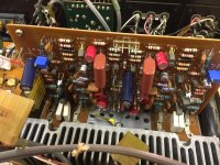
Is this success??
It's odd when you return to a project what strikes you. Installing the Bias pots as in these pictures means min bias / max voltage is at opposite ends of the VR
It takes some time to have the bias voltages stabilise, I'm using a Fluke 115 on the mV range
Still OK with the bulb-less technique just make sure the meter is correctly connected as per the service manual. Here's my 'procedure' for what its worth
- No Power Vfets,
- Power on Pre not connected to the Power
- Set the 20v line
- Set Bias to the highest voltage, +/- 60 odd volts relative to earth
- Install V-fets (do I have to say with power off?? 😀 )
- and a meter (or two) connected measuring the bias mV (between test point and speaker +ve)
- Power on watching the bias mV readings - they should plummet. If not below 75mV in a couple of seconds [OFF] (75mV was the original running point)
- Pick a channel and increase the bias, with multi turn pots you will be making maybe 10+ turns before you reach the sweet spot, again if NOTHING is changing stop and check you're measuring the right thing - that's never happened to me 😵🙄
- According to the "Dutch service bulletin" Bias should be set to 45mV not 75mV as per the service manual. I chose 35mV for a bit, while everything settles down (an abundance of caution?) It does indeed take 15 minutes to 'stabilise' don't skimp on that.
Couple of nuances,
Morning after - Bias on a quiet amp (turned on but no signal after 30 mins now gets to 30mV not 35mV - Conclusion: there is some scope here, given the original spec was 75mV and revised limit is 45mV Lets see how burn in goes. If that's even a thing on a 45y/o amp 🙂 😀
To crow about it a bit, the volume control is just peachy! No scratchy noise whatsoever, pleased with that process (soak in IPA then add contact lube)
For comedy value I added loudness and turned the bass up to 10 and yes through my Castle Harlech's the floor does indeed go wobble - surprise for what's supposed to be a bit weedy - much OOOooommmphh!!
To think the TA 4650 / 5650 was "just something you could buy" - and from a mainstream manufacturer at that, tells a tale... Of course 'proud father' syndrome applies here. Get your own and find out 😀
I think that's all folks - end of thread
Andy
Well done 👏 you. Yes the bass is relatively good for a 40yr old amp. I use some IPL Acoustic Transmission line speakers and they have some rumble to them, even at low volume.
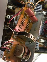
Andy,C and D boards
C board and D boards
These come as a pair by virtue of all the wire wrapping linking them together
The C board is tone control, nothing in here needs touching really, just the standard scrub and so on
The D Board – marked as control in the service manual
C210, C260 – 10uF / 25v replaced with 4.7uF / 63v film
C209 C259 – 470uF / 6.3v (New type) replaced with 470uF /16v poly
And clean the switches out of course
Without thinking I initially elected not to replace RV202/252 but, as I'm writing this, I think that's actually still standard enough to be replaced. It's also the balance pot so pretty important
Andy
Please check polarity of C209. The Silk Screen may be incorrect again, I have my -ve facing upwards when the panel is lowered down. I also checked on the photos I took before replacing caps.
- Home
- Amplifiers
- Solid State
- Another Sony TA 4650 V-fet thread