Hi guys
I am recapping my mark levinson 33H
As I star with the output stage board I have looked for week links
I wish to upgrade the emmiter resistors to non inductive and non magnetic ones and if it's possible to ultra low noise ones.
I don't have any experience in this specific point of upgrade so I don't
Know what to expect by sound characters.
I have heard great things about vishay mils resistors and ohmite audio gold resistors.
Did any one compare between those 2 ones ?
What are the sound characters did you got by upgrading emmiter resistors?
Values that I need are:
0.22 ohm 5w now installed cw5 resistors)
0.33 ohm 10w (now installed cw10 resistors)
10 ohm 5w (now installed vishay NS-5 non inductive)
Best regards
Nehoray
Attachments
Hi Nehoray,
The voltage gain is slightly less than one in that circuit. So low noise is a concept that doesn't make any sense at all there. Additionally, I'll assume the resistors are the standard wire-wound box type. Wire-wound resistors are not noisy to begin with. In short, I would leave them be.
I have tested non-inductive "plate" resistors and found them to have a strong positive temperature co-efficient. Probably best to avoid them. In addition, the inductance is not only low-ish, but has been compensated for in the design. Best to just leave them in place as there is zero advantage in replacing them.
Most name brand parts are simply "name brand" and do not have any advantage over other parts with the same construction. I restore and upgrade high end audio for a living, and I spend a lot of time pulling "upgrade" parts out that don't fit and may even be worse than the parts the manufacturer used to begin with. I also have to write-off a few pieces every year that were damaged beyond reliable operation by folks installing "audiophile approved" parts that damage the PCBs. My favorite stupid move are the capacitor installations where the capacitor leads are much larger than original. The idiots will drill out plated through holes to fit the new parts, then wonder why it no longer works or works well.
So in a nutshell, if the part doesn't fit in the existing holes or mounting space - you cannot use it. Often, upgrade brands do not offer improved performance and the name isn't important, its the construction and materials common to that class of part. I have over 40 years experience and well over $100,000 in test bench equipment to back me up. Some of that gear is brand new as I stay up to date.
Hopefully this helps you and anyone else out on the "upgrade path". Use your head and common sense, most of what is written on the web is nonsense written by complete hacks. If the recommendations are only backed up by listening tests - run. These days, improvements can be measured past where you can hear them. Humans make crappy test instruments, but can be good at instantaneous A-B comparisons - sometimes.
-Chris
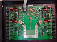
Those look like low-inductance metal-oxide power resistors in the picture you attached. Those are probably the best one can use in those locations. If there was a better option, ML would have used it, I'm sure. I would not change any of the resistors.
Replacing the big electrolytic cans is a good idea. Maybe other electrolytics, too. I would leave all the rest alone.
Replacing the big electrolytic cans is a good idea. Maybe other electrolytics, too. I would leave all the rest alone.
All Mark Levinson gear was carefully designed and engineered, you'll not improve it in any meaningful way and it's not terribly unlikely that you will break it. If you don't like the way a largely blameless amp sounds sell it and buy something else.
I admit I don't which is why I run a sextet of hybrid dht SE amplifiers which no one would ever claim were blameless.
I admit I don't which is why I run a sextet of hybrid dht SE amplifiers which no one would ever claim were blameless.
Thanks all ...
Hi Nehoray,
Sometimes you can follow advice on how to improve junk - like an NAD for example. But you will often, as has been pointed out, cause more damage than improvement without training on at least how to solder. But why try to improve junk to start with??
Anyway, do as little as you can with your amplifier. If it has a problem, take it to someone who is a good audio technician, respected with a track record.
-Chris
Hi Nehoray,
It will, but not in a meaningful way. But I do not have time or space to teach you how amplifiers really work and your question rather demands that. I firmly believe that you need to know how to design an amplifier well before you can second guess a designer that gets paid to do this work. That, and you need to understand components as well. I have yet to see a person who goes on about modifying equipment their way who knows the first thing about what they are talking about if they also do not have really good test equipment and the knowledge of how to use it and what they are looking at.Can you explain more about why non inductive resistor won't change a thing ?
Sometimes you can follow advice on how to improve junk - like an NAD for example. But you will often, as has been pointed out, cause more damage than improvement without training on at least how to solder. But why try to improve junk to start with??
Anyway, do as little as you can with your amplifier. If it has a problem, take it to someone who is a good audio technician, respected with a track record.
-Chris
Hey Kevin,
You run what you do partly out of curiosity and interest, and out of pride for the good work you do. Look at Nelson Pass' career. He has gone from various design ideals to where he is now. I'd say the man is following his interests and not on the path of a zero percent distortion amplifier. That's a crowd. He is enjoying his work and makes no apologies.
Enjoy and have fun!")
You run what you do partly out of curiosity and interest, and out of pride for the good work you do. Look at Nelson Pass' career. He has gone from various design ideals to where he is now. I'd say the man is following his interests and not on the path of a zero percent distortion amplifier. That's a crowd. He is enjoying his work and makes no apologies.
Enjoy and have fun!
Yep -- how do we attach a 'Sticky' to anatech's initial post? Very well put...
Hit the

Actually you sticky THREADS, not Posts. We (mods and community) might ask to re-post anatech's words as a new thread.
And FWIW, anatech is a moderator and can do his own sticky-stuff. But may be too modest.
Another Bravo to Chris for that second post!
He covered it quite well from several angles.
My thoughts exactly.
While this IS a "diy" audio site, it encompasses a plethora of individuals with various degrees of knowledge in electronics fundamentals and design.
And yes, it extends from professionals, down to backyard mechanics, and even Mrs Hooseberry, the elderly housewife.
Also a fact is,... not everything is honestly worth repairing/upgrading/messing with.
As Kevinkr pointed out, some equipment is not justifiable for upgrades.
The overthinkers seem obsessed with attempting to better what is already designed into a given product, and the many online blogs (and snake oil suggestions) further push people towards tearing into something.
"Oh, so you think you know more than an established design lab in some corporation?"
As expected, the results run from "wow what a difference"(in their mind) to complete failure.
The widespread "recapping" idea is one of those features.
But, alas, the stubborn will remain stubborn.
Levinson is not garbage quality brand... although they sure do like to use lots of parts...
> I am recapping my mark levinson 33H
Make sure you don't put fancy low-ESR aluminium caps for your decoupling. They will resonate with the film caps placed in parallel.
> I wish to upgrade the emmiter resistors to non inductive and non magnetic ones and if it's possible to ultra low noise ones.
Why? Listen to anatech instead lol.
Your resistors are good quality wirewounds with "all welded" construction. I assume this means the resistance wire is welded to the endcaps, which is much nicer than crimped-on endcaps. I remember a topic somewhere here where a guy hunted some distortion in his amp and it turned out to be an emitter resistor with badly crimped-on endcaps that created nonlinear resistance. So: welded = good.
Also they went to the trouble of threading the leads through cute little ceramic pcb standoffs, which should give more "breathing room" to the resistors (for that "airy" sound) and it doesn't barbecue the pcb when the resistors get toasty like it did in my Cairn amp before it died. Good.
Personally I would be very very wary of changing the emitter resistors, since using something with different inductance would probably require adjusting the amplifier compensation.
If you put two capacitors in parallel, they each have an ESR (equivalent internal series resistance) and some inductance due to the capacitor construction and the PCB traces or planes connecting them in parallel, so you get this:

If you squint a little bit, it is apparent that while the capacitors are in parallel to filter the power supply, to study how they will resonate, they appear as being wired in series. So, this is a series RLC resonant circuit, with:
L and R = sum of all the inductance and resistance in the loop
C = both capacitors in series, so if one is much larger than the other, it'll approximate as the smaller one.
So you can calculate its frequency response and damping factor (the formula for damping factor is in the link), and if there is not enough damping, you can get pretty nasty resonance peaks like so:

In the time domain, these peaks translates into ringing.
Note this is a high frequency example between ceramic caps, but it's the same in audio circuits, the capacitors have larger values, but the inductance is also much larger, since traces are used instead of power planes.
So, a dude sees a power supply board, and there is a film cap on the output. It is connected through some wires (adding inductance) to another board which also has a film cap on it. But both boards have cheap general purpose electrolytic caps on them, with enough ESR to provide enough damping, so it works fine.
Then, having heard something from the internets, he replaces one of the "not gold plated enough" electrolytic caps with, say, a Panasonic FC which has super low ESR, or even worse an enormous audiophile film cap which has like 1 mOhm ESR and an inductance as huge as its size.
And that low ESR nukes the damping and creates a high Q resonant circuit with the wiring inductance and the other caps, and that throws a nice burst of 1-2 MHz RF every time one of the rectifying diodes (or the output power transistors) switches which kicks the butt of all the analog circuits in the box.
And then the dude posts "I don't like Panasonic FC they sound harsh".
So yeah, if you don't know what "series RLC circuit damping factor" means, you should of course use high quality caps that will last a long time, preferably 105°C in hot places, but DO NOT use the LOW ESR/LOW Z caps or yuge audiophile film caps unless you do the math
If you squint a little bit, it is apparent that while the capacitors are in parallel to filter the power supply, to study how they will resonate, they appear as being wired in series. So, this is a series RLC resonant circuit, with:
L and R = sum of all the inductance and resistance in the loop
C = both capacitors in series, so if one is much larger than the other, it'll approximate as the smaller one.
So you can calculate its frequency response and damping factor (the formula for damping factor is in the link), and if there is not enough damping, you can get pretty nasty resonance peaks like so:
In the time domain, these peaks translates into ringing.
Note this is a high frequency example between ceramic caps, but it's the same in audio circuits, the capacitors have larger values, but the inductance is also much larger, since traces are used instead of power planes.
So, a dude sees a power supply board, and there is a film cap on the output. It is connected through some wires (adding inductance) to another board which also has a film cap on it. But both boards have cheap general purpose electrolytic caps on them, with enough ESR to provide enough damping, so it works fine.
Then, having heard something from the internets, he replaces one of the "not gold plated enough" electrolytic caps with, say, a Panasonic FC which has super low ESR, or even worse an enormous audiophile film cap which has like 1 mOhm ESR and an inductance as huge as its size.
And that low ESR nukes the damping and creates a high Q resonant circuit with the wiring inductance and the other caps, and that throws a nice burst of 1-2 MHz RF every time one of the rectifying diodes (or the output power transistors) switches which kicks the butt of all the analog circuits in the box.
And then the dude posts "I don't like Panasonic FC they sound harsh".
So yeah, if you don't know what "series RLC circuit damping factor" means, you should of course use high quality caps that will last a long time, preferably 105°C in hot places, but DO NOT use the LOW ESR/LOW Z caps or yuge audiophile film caps unless you do the math
I have made some experiments on this:
< http://www.hoffmann-hochfrequenz.de/downloads/experiments_with_decoupling_capacitors.pdf >
Gerhard
< http://www.hoffmann-hochfrequenz.de/downloads/experiments_with_decoupling_capacitors.pdf >
Gerhard
- Home
- Amplifiers
- Solid State
- Low noise Emmiter resistors