Hi Nehoray,
You have received excellent viewpoints and advice from all parties. Most have actual real experience in this field. "Audio" isn't something that is easy. People in this field are real professionals who know as much as any other professional pursuit. They often have a great deal invested in training and equipment. You should accept advice from these people just as you would from a good lawyer or anyone else who spent a lifetime learning with academic experience (as opposed to someone who is just an internet reader who hacks around and just reviews equipment).
It's really up to you. You sound like you are determined to get in there and change something. One thing I will caution you about is increasing the capacitance of capacitors. I have often reduced the capacitance when I have had to replace them so that the switching spikes are reduced (better HF response from the capacitor). The factory capacitance being grossly greater than required. Bedinni amplifiers can be like that. There is a happy range for capacitance where deviation either way can reduce performance. Same for all power supplies. The reasons why are a course in electronics, which I am not about to attempt to teach.
The people who designed your amplifier were well paid professionals with access to a lab and good test equipment. University trained and field experienced people. Why would you listen to arm chair critics with zero education by comparison?
You are actually talking to some of those kinds of professional or well studied people here who are trying to help you. Asking questions is fine, and you are getting answers. peufeu and gerhart have good experience here, and they are right. Learn from them.
-Chris
Not in every case. Good quality capacitors have excellent seals and are used lightly in good designs. There is a lot of electrolyte fluid in power supply capacitors and they rarely need replacement. Want to blow money down the drain?? Go for it.Don't you think that after 20 years of service I shouldn't replace the electrolytic capacitors ?
You have received excellent viewpoints and advice from all parties. Most have actual real experience in this field. "Audio" isn't something that is easy. People in this field are real professionals who know as much as any other professional pursuit. They often have a great deal invested in training and equipment. You should accept advice from these people just as you would from a good lawyer or anyone else who spent a lifetime learning with academic experience (as opposed to someone who is just an internet reader who hacks around and just reviews equipment).
It's really up to you. You sound like you are determined to get in there and change something. One thing I will caution you about is increasing the capacitance of capacitors. I have often reduced the capacitance when I have had to replace them so that the switching spikes are reduced (better HF response from the capacitor). The factory capacitance being grossly greater than required. Bedinni amplifiers can be like that. There is a happy range for capacitance where deviation either way can reduce performance. Same for all power supplies. The reasons why are a course in electronics, which I am not about to attempt to teach.
The people who designed your amplifier were well paid professionals with access to a lab and good test equipment. University trained and field experienced people. Why would you listen to arm chair critics with zero education by comparison?
You are actually talking to some of those kinds of professional or well studied people here who are trying to help you. Asking questions is fine, and you are getting answers. peufeu and gerhart have good experience here, and they are right. Learn from them.
-Chris
Yes indeed ! My network analyzer agrees. Ironically, the capacitor combos with the smoothest response and no ringing tend to be cheap and unremarkable: some electrolytics with a bit of ESR, not too low, not too high, so not exotic or expensive, plus one MLCC per pin like 1µF for HF. On a higher inductance board without ground plane, like in the amplifier this topic is about, it's even cheaper, since you need a bit more ESR to compensate for the inductance of long traces.
Also I second anatech's recommendation to not replace caps with larger value, especially on boards that are not the power supply board. On the amplifier board there will be a bunch of electrolytics. If they are replaced with larger values, these will draw in higher rectifier current pulses on the traces where you don't want them, on the amplifier board, so you get more hum.
The flashy violet cans like OSCONs are very much like bright purple paint : they have a purpose, and correctly used for this purpose they are truly amazing, but don't put it everywhere in your house.
True audiophiles use film bypass caps that have more inductance than the big snap-in cans they bypass though 😉
Last edited:
Thank you all for your replies and explanation
I didn't aware of all that
I wish to bless you all: may God gives all your heart is wishes for...
I didn't understand one thing about the graphs that you have show
All of the nasty parts looks so far away of the audio band.
So why it's still a problem?
Chris
I don't lie to you I did increase the capacitance at two points in the amplifier.
Hope they will not cause any problems...
Regarding to the original capacitors, all the originals are ultra low esr
So I uses panasonic FS and nichicon UHE
The biggest increasment of the capacitance was the electrolytic on the output stage board the original was united chemi-con URZA
Real ultra low esr and huge size !!! And 330uf
Unfortunately those capacitor are no longer available
So I turn in to mundorf 1500uf
Peufeu in this amplifier there isn't any bunch of electrolytic only 4 units of 330uf.
One of the best things in this amplifier that it uses as minimum electrolytics as it can.
Hi Nehoray,
I would have to examine the schematic and know exactly what you increased to make any comment. Suffice to say, I hope they physically fit on the PCB properly in the space provided. If they don't, remove them and install something that does.
All good capacitors will perform well. You can't hear a difference between them because they do not develop a voltage across the terminals - unless they are defective. In audio circuits, ESR is totally unimportant. DA is what matters. ESR is important in power supplies and supply bypass applications.
I would say that people who can hear the difference between good electrolytic capacitors are hearing things, because evidence does not support that claim at all. I've also tried, and I do listen to my work as well as measure it.
Also, capacitors are not necessarily bad in the signal path. Bypassing or not installing a DC blocking capacitor from an amplifier input, or preamp (or signal source) output is completely irresponsible. I'll go further and claim it is stupid. I have had preamplifiers go "DC" on one channel, and the amplifier successfully destroyed a woofer by burning it. It was a well known brand that didn't use blocking capacitors in preamp outputs or amplifier inputs. The DC servo in the preamp went bad. These things do happen, expect trouble. For the sake of some ad copy, one person paid for a new woofer and amplifier repair that didn't have to happen. The speaker could have caused a fire, but it didn't. The woofer did burn.
-Chris
Thanks again for your reply Chris
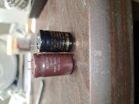
United chemi-con URZA are very lage cans, as a matter affect they have the size of snap-in capacitor, just that URZA has called radial because of its legs.
The legs spacing and the holes in the PCB is 100% feet
The funny thing is that the URZA is even larger by it height
Yes those capacitors placed in the power supply Rail. So such low esr will do make a difference.
I will take advantage of this post and ask:
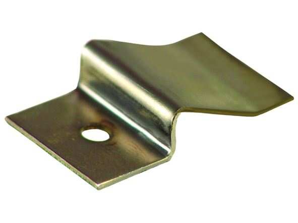
In the oscillator board the thermal pads looks OK
Leave them as it is or should I replace them for new ones ?
BTW this heatsink is so hot that not all of the owners of the ml33h knows but the front panel is also uses as heatsink for this oscillator.
United chemi-con URZA are very lage cans, as a matter affect they have the size of snap-in capacitor, just that URZA has called radial because of its legs.
The legs spacing and the holes in the PCB is 100% feet
The funny thing is that the URZA is even larger by it height
Yes those capacitors placed in the power supply Rail. So such low esr will do make a difference.
I will take advantage of this post and ask:
In the oscillator board the thermal pads looks OK
Leave them as it is or should I replace them for new ones ?
BTW this heatsink is so hot that not all of the owners of the ml33h knows but the front panel is also uses as heatsink for this oscillator.
Attachments
Hi Nehoray,
As long as the capacitor fits on the board like the old one, you're fine assuming the value isn't increased much. Higher voltage is better if you have to make a choice.
I am not a fan of sil-pads and generally use mica and grease to replace them if I took them off. But, don't take transistors off just to replace the sil-pads. For special sil-pads cut for a line of transistors, if it is in good shape, I clean with Methyl Hydrate, add a thin coat of thermal compound to the transistors and reinstall everything. It goes without saying that you clean the mounting surface and transistors too. Make sure you do not over-tighten the transistors! Many people do. That can cut the sil-pad, strip the threads or break the transistor (or warp it and break the die inside). Each case has a mounting torque. On-Semi has a paper on this, originally by Motorola. Read it please.
-Chris
Why ? Don't you think that after 20 years of service I shouldn't replace the electrolytic capacitors ?
As long they don't leak then not.
Capacitors at least those which have some quality from beginning are designed to hold at least 15 Years, And a company as ML does not use cheap stuff..
If the caps leak then exchange with same brand and original from ML, do not use other because then the sound will drift away from what it was or has been or was designed for.. Has been said before already, sell the amplifier and buy one which fits what you think is good.
Or DIY your own one..
Good luck
Chris
Chris Thanks for the info
ML preferred to work with silicon pad with all the transistors mount on it.
However I didn't understand by your answer if this pad does not damage wouldn't you replace it as a maintaining ?or not ?
Hero I don't have enough knowledge to build my own amplifier
And I have high demands from an amplifier.
Mark levinson 33H was a dream of mine for 20 years when I have started my audiophile path.
Beside of this nice story I have very difficult speaker to drive
As stereophile described this amplifier it's act like almost perfect power source.
For me it's almost perfect amplifier, the only disadvantage or big advantage is that this amplifier has no character not warm sounding not cold one... just straight wire with a gain.
Many years ago I had MBL 8011S which has tube sounding solid state... sometimes I miss that warmth and it's seems that the only solution to work with the 33H it with tube pre amplifier
If you have any recommendations for tube preamp which has low output impedance and fully balanced I will try it with my setup.
Regarding to modifications by power supply capacitors
Well I don't have the knowledge like you guys but I believe what I am hearing
Yes everything is scientific I do believe in that also
I am not a man of snake oil.
One of the tests that I have made was with my previous amplifier
MBL 9007 which was very nice one. The amplifier came with a poor
Brand made in China I belive 33000uf each
I have replace those by epcos 47000uf, to tell you the truth the change was minor and not worth the money at all.
One of my friends told me to try and bypassing them by mundorf silver oil 4.7uf each.
After installing the mundorf the sound difference was so big that you couldn't go back. The improvement was bigger than replacing xlr or speaker cable. As a matter it was the most significant tweak that I have heard.
One small example that you can try it for yourself:
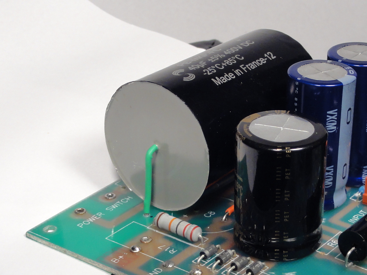
Lot's of amplifiers comes with screw type capacitors
Those capacitors comes with screws with the manufacturer which are magnetic ones, please to replace those for brass screw and hear the difference, I don't know if it's a matter of magnetic or a matter of electrical conductivity, but still this experiment so impressed me that
I have ask one of my friends to make screws by tellerium copper
For all the parts that holds electrical connections
Brass has 15% conductivity
Tellerium copper has 95% conductivity
If you think about it all the threads have huge contact surface erea.
But you can try it for your self.
ML preferred to work with silicon pad with all the transistors mount on it.
However I didn't understand by your answer if this pad does not damage wouldn't you replace it as a maintaining ?or not ?
Hero I don't have enough knowledge to build my own amplifier
And I have high demands from an amplifier.
Mark levinson 33H was a dream of mine for 20 years when I have started my audiophile path.
Beside of this nice story I have very difficult speaker to drive
As stereophile described this amplifier it's act like almost perfect power source.
For me it's almost perfect amplifier, the only disadvantage or big advantage is that this amplifier has no character not warm sounding not cold one... just straight wire with a gain.
Many years ago I had MBL 8011S which has tube sounding solid state... sometimes I miss that warmth and it's seems that the only solution to work with the 33H it with tube pre amplifier
If you have any recommendations for tube preamp which has low output impedance and fully balanced I will try it with my setup.
Regarding to modifications by power supply capacitors
Well I don't have the knowledge like you guys but I believe what I am hearing
Yes everything is scientific I do believe in that also
I am not a man of snake oil.
One of the tests that I have made was with my previous amplifier
MBL 9007 which was very nice one. The amplifier came with a poor
Brand made in China I belive 33000uf each
I have replace those by epcos 47000uf, to tell you the truth the change was minor and not worth the money at all.
One of my friends told me to try and bypassing them by mundorf silver oil 4.7uf each.
After installing the mundorf the sound difference was so big that you couldn't go back. The improvement was bigger than replacing xlr or speaker cable. As a matter it was the most significant tweak that I have heard.
One small example that you can try it for yourself:
Lot's of amplifiers comes with screw type capacitors
Those capacitors comes with screws with the manufacturer which are magnetic ones, please to replace those for brass screw and hear the difference, I don't know if it's a matter of magnetic or a matter of electrical conductivity, but still this experiment so impressed me that
I have ask one of my friends to make screws by tellerium copper
For all the parts that holds electrical connections
Brass has 15% conductivity
Tellerium copper has 95% conductivity
If you think about it all the threads have huge contact surface erea.
But you can try it for your self.
Motorola AN-1040 is the paper on transistor mounting.
https://www.nxp.com/files-static/rf_if/doc/app_note/AN1040.pdf
Attachments
What's in there is fine. Wire-wounds tend to be low noise, and there's no gain in that circuit. Also, the tiny amount of resistance involved in those resistors also means there'll be no noise to worry about.
Only 9 views / downloads for AN1040 that PRR linked to?! This should be required reading for every DIYer out there. I wish we could host stuff like this.
-Chris
-Chris
Only 9 views / downloads for AN1040 that PRR linked to?! This should be required reading for every DIYer out there. I wish we could host stuff like this........
It was llwhtt's cite; I just found it and re-posted it into DIYA's file storage.
(Because I only found one copy in Google and I have seen way too many good app-notes lost by corporate reorganization/clean-out.)
And you can lead a horse to water but you can't make him drink. Or think.
OK, I'll add one -- even though I think I have it (somewhere 😉) from my Motorola-subscription days -- and stupid Windows keeps whining about the end of my hard disk ..
Now up to 19 .. Thanks PRR!
Cheers
Now up to 19 .. Thanks PRR!
Cheers
Last edited:
Hi PRR,
Yes, and thank you for the detective work.
Everyone,
Now we need a reasonably priced torque screwdriver for the masses! I will say one thing for you. The mounting torque for semiconductors is something just past "snug" by feel. It isn't nearly as tight as one might think. If the grease squeezes out evenly around the part (light application of grease), and it is just past tight by rotating the shaft of the screwdriver with your fingers (not the handle, the skinny shaft), you're probably close to the right tension on the part. Remember that you must avoid bending the case, and that is really easy to do with TO-220 case transistors. Warping the tab can break the die attach, or crack the die (the actual silicon transistor).
I do use a torque driver. It goes "click" when the right tension is reached. If you don't have one, even tension is very important on something like a TO-204 (TO-3 for us old farts) package. I also use the torque driver on RF enclosure tops and other situations. Most stuff only needs the hardware to be snug, not very tight. It would be very nice not to see another stripped screw or hole!
-Chris
The mounting torque for semiconductors is something just past "snug" by feel. It isn't nearly as tight as one might think. If the grease squeezes out evenly around the part (light application of grease), and it is just past tight by rotating the shaft of the screwdriver with your fingers (not the handle, the skinny shaft), you're probably close to the right tension on the part.
-Chris
Indeed Chris!
I tell people that we're not installing plumbing here, that might leak.
Or torquing down a head block on an old Chevy.
You have to have a "feel" for things like this, and a mind that kicks in with learned experience from memory.
I use torque screwdriver by Sturtevant Richmont. It's a 29 piece set from McMaster-Carr. It's a bit pricey, $305, but it gets used a lot as it's the only way to do the job correctly. The driver may be available separately.
Craig
Craig
If you put two capacitors in parallel, they each have an ESR (equivalent internal series resistance) and some inductance due to the capacitor construction and the PCB traces or planes connecting them in parallel, so you get this:
View attachment 942591
If you squint a little bit, it is apparent that while the capacitors are in parallel to filter the power supply, to study how they will resonate, they appear as being wired in series. So, this is a series RLC resonant circuit, with:
L and R = sum of all the inductance and resistance in the loop
C = both capacitors in series, so if one is much larger than the other, it'll approximate as the smaller one.
So you can calculate its frequency response and damping factor (the formula for damping factor is in the link), and if there is not enough damping, you can get pretty nasty resonance peaks like so:
View attachment 942592
In the time domain, these peaks translates into ringing.
Note this is a high frequency example between ceramic caps, but it's the same in audio circuits, the capacitors have larger values, but the inductance is also much larger, since traces are used instead of power planes.
So, a dude sees a power supply board, and there is a film cap on the output. It is connected through some wires (adding inductance) to another board which also has a film cap on it. But both boards have cheap general purpose electrolytic caps on them, with enough ESR to provide enough damping, so it works fine.
Then, having heard something from the internets, he replaces one of the "not gold plated enough" electrolytic caps with, say, a Panasonic FC which has super low ESR, or even worse an enormous audiophile film cap which has like 1 mOhm ESR and an inductance as huge as its size.
And that low ESR nukes the damping and creates a high Q resonant circuit with the wiring inductance and the other caps, and that throws a nice burst of 1-2 MHz RF every time one of the rectifying diodes (or the output power transistors) switches which kicks the butt of all the analog circuits in the box.
And then the dude posts "I don't like Panasonic FC they sound harsh".
So yeah, if you don't know what "series RLC circuit damping factor" means, you should of course use high quality caps that will last a long time, preferably 105°C in hot places, but DO NOT use the LOW ESR/LOW Z caps or yuge audiophile film caps unless you do the math 😀
+10
Jan
- Home
- Amplifiers
- Solid State
- Low noise Emmiter resistors