I've replaced the diode with a jumper and everything is the same. I'm going to replace the 5.6r with a jumper now.
What do you mean by SE?
I've also replace all the transistors and nothing's changing.
Would it make sense that the 560r were a 56k? Maybe they got it wrong, that happened to me here. The orange and brown stripes looks the same. I had to desolder mine to realize it.
I don't want to turn the pot the its minimum...It's going to fry stuff. As I reduce resistance, more voltage at emitters output it gets. Actually what I'm going to do is replace it with a 1M pot one.
Es más rápido ensamblar un amplificador de este tipo en cartón que describir cómo funciona 
It is faster to assemble such an amplifier on cardboard than to describe how it works
According to datasheet BD131 / 132, this amplifier cannot operate at 8 ohms. Only 15 or more.#10
It is faster to assemble such an amplifier on cardboard than to describe how it works
According to datasheet BD131 / 132, this amplifier cannot operate at 8 ohms. Only 15 or more.#10
Last edited:
I drafted your circuit in LT Spice - a stab effort from what you provided. I have been flexible with some component values and types. The main difference between this and the circuit OldDiy posted is a resistor connecting the base of MC150 to the supply rail which I included.
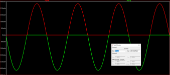
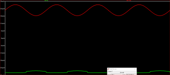
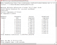
At low output the THD at 20kHz is amazingly good for such a simple circuit - 0.1 %. Actually the value of the input trimpot in the simulation is 347k.
The .asc file and a plot of the emitter currents which shows the output transistors turn off virtually at the crossing point. Through that point R9 and R10 remain in conduction so there is hardly any notch distortion.
I have yet to check for stability issues on this simulated version.
Attachments
Last edited:
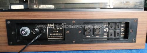
I think I said 225 but mine is 275, sorry. This:
Solid State Unit Amplifier EF-275 Ampl/Mixer Bettor, Industr
It is also quadraphonic. It says 2x12w 8ohm. For the extra speakers, when selected the quadro mode with the switch, there is a wound resistor at the switch board that I guess it does some stuff.
This amp comes with BD175 BD178, although the board says clearly BD131 BD132.
Am I f*cked? Please tell me I'm not.
Well, the problem was the trimmer. I put a 16mm pot there with wires and no problem at all. It's crazy because half supply is achieved with less resistance than with the original trimmer. So this trimmer is the biggest troll of the whole universe. Crazy.
Thank you mjona for taking your time, I really appreciate it.
Last edited:
If the original transistors were BD131 and BD132 these are 3A and 11W rated. The BD175 and BD178 are 3A and 30W rated.
You can still source BD131 and BD132 from old stock suppliers like Silicon Ark. These are 60MHz devices whereas the BD175 and BD178 are only 3MHz devices.
The quadraphonic function is probably to blame for the demise of the BD131 and BD132 due to increasing the load with running 4 speakers - moreso if any of these has 4 Ohm impedance.
The problem with the BD175 and BD178 replacements is that phase starts to alter at a much lower frequency than with the original devices and unless the stability compensation is altered there will be a problem with the amplifier.
I used a capacitor of 100nF in parallel with the load in my simulation. The BD139 and BD140 were the closest type I could find for modelling the BD131 and BD132.
Some modern driver transistors such as MJE15032 and MJE15033 are characterized for high frequencies, these are 30MHz devices still a little short in comparison with BD131 and BD132.
I have not looked for or considered others in that category that might be better. Others following this discussion could have ideas in that regard.
This amp comes with BD175 and BD178. There's a video on youtube where you can see the same unit as mine also with the 175 and 178.
I got some BD131 & BD132 for replacement because that's what the board says. It's written on it. So I thought that these are the transistors the amp was design for it, and that for some reason they used others (BD175 & BD178) just for availability or something.
I see, so better keep the 131 & 132 instead of the 175 & 178. I'm going to use it with just two speakers. Can I use a couple of 8ohm speakers with the 131 & 132?
Ah, I forgot to mention that the 5,6r reads 6r. Which is a bit above the 5% tolerance. Since it is in a crucial place I'd like to replace it, should I get a 1w resistor or a low one like 1/2w. At first I thought that the more watts the better, but then started to think that maybe that heat is used in order to do some magic and keep the bias and all those thermal running concepts and stuff. I'm learning. Slowly, but learning.
BTW, the quadraphonic wiring looks weird. Instead of duplicating each Right and Left channel, it triplicates one channel and the use the other for just one channel. Maybe someone manipulated it before.
I still can't understand what the hell happened to the trimmers. They have resistance but they mess everything up somehow.
Thanks a lot. Especially you and OldDIY. I really appreciate it.
8 Ohm speaker loads were standard in the 1970's in view of the power rating of the BD131 and BD132 it would pay to use speakers with good sensitivity and simple cross over networks.
A PTC fuse (Also known as Polyfuse) might be a useful circuit protection in the speaker out line.
A 1 Watt resistor is more likely to stay within the 5% tolerance than 0.5 Watt one.
Some of the trimmers from the 1970's are bigger than one's thumbnail and probably contaminated by airborne matter, such as oxygen, moisture, household cleansers and sprays etc - basically anything one can smell.
The EF1 circuit is critically sensitive to the load resistance depending on the Hfe output transistors (the more, the better). Selection of the output pair is required. A frequency of 3 MHz is sufficient. A small DC current of 30mA passes through the speaker (Bootstrap).
The peculiarity of this circuit is the initial current of the upper output transistor 20mA through the feedback resistor 680 + 22 ohm.
A simple full-range speaker load is recommended. Preferably with a resistance greater than 8 ohms.
The peculiarity of this circuit is the initial current of the upper output transistor 20mA through the feedback resistor 680 + 22 ohm.
A simple full-range speaker load is recommended. Preferably with a resistance greater than 8 ohms.
Last edited:
Well, the problem was the trimmer. I put a 16mm pot there with wires and no problem at all. It's crazy because half supply is achieved with less resistance than with the original trimmer. So this trimmer is the biggest troll of the whole universe. Crazy.
Well, that's exacly what I suspected when I formulated my question in #41. Old, non encapsulated trimpots usually go open after decades.
Best regards!
mjona said:A PTC fuse (Also known as Polyfuse) might be a useful circuit protection in the speaker out line.
Would a 900mA work? Or is it too much?
The EF1 circuit is critically sensitive to the load resistance depending on the Hfe output transistors (the more, the better). Selection of the output pair is required.
Do you mean I need to match the couple 131 132 regarding hfe?
So if I have understood ok: the 131 132 pair might sound better due to the phase altering thing happen later than the 175 178. But the latter gives more output.
Kay Pirinha said:Well, that's exacly what I suspected when I formulated my question in #41. Old, non encapsulated trimpots usually go open after decades.
Yeah, I know about that. But they aren't open. I desoldered and tested them. They read resistance along the whole swap. But for some reason, when they are in the circuit they behave badly. It's like they change their behaviour when electrons are flowing.
It's like they change their behaviour when electrons are flowing. - Poor moving contact (oxidation).
After selecting a pot, you can measure it and set a constant resistor of the closest value.
Selection of the output pair is required. - Select according to the maximum (the same for a pair) Hfe at a current of 1a.
After selecting a pot, you can measure it and set a constant resistor of the closest value.
Selection of the output pair is required. - Select according to the maximum (the same for a pair) Hfe at a current of 1a.
- Status
- This old topic is closed. If you want to reopen this topic, contact a moderator using the "Report Post" button.
- Home
- Amplifiers
- Solid State
- Mid 70's amp distorting pretty badly. High crazy base voltages 20v¿?