Check again according to # 10.
There may be jumpers at the top that connect the bottom conductors.
From each output, go to the adjacent part, from it to the next (or several, if the connection branches.
You can number all the points, assign point numbers to the pins of the part, and then connect the same points on the schematic.
There may be jumpers at the top that connect the bottom conductors.
From each output, go to the adjacent part, from it to the next (or several, if the connection branches.
You can number all the points, assign point numbers to the pins of the part, and then connect the same points on the schematic.
Last edited:
The main board of this amp contains both the control section (balance, vol and eq) and power stage. I can't really tell where the control ends and output stage starts.
The signal goes directly to the balance and vol pots (all pots dual). The vol pots has a couple of SC109b.
Right before the input in my schematic there is a sc109b, just one. At this point is hard to trace it because the signal goes to the control section (eq and stuff).
I will try to identify each part but it looks really messy.
So this amp uses 4 transistors (BD131, BD132, MC150,SC107B) + 2 transistors (SC109b) per channel. The SC109Bs look like they belong to the control section. At least the first couple (the ones right at the vol pot).
To begin with, you are interested in the circuit around (BD131, BD132, MC150, SC107B). In my opinion, the diagram may be similar to # 10.
But this is inaccurate.
But this is inaccurate.
Make sure those pots are not open, it would be a common failure in amplifiers of this age.
Schematic still does not look right to me. I think OldDIY is steering you in the right direction.
When everything is finally working correctly the voltage between the emitters of the output transistors and ground should be close to half the supply voltage. It might drift a bit as the transistors heat up so check that carefully.
Some of those small signal transistors may be bad. I am not familiar with the specific ones you have, but I have on occasion found the Vbe test misleading. You should also check base to collector. (Should get reading close to what you see on b-e, and none in the other direction.) Open base you should get no current across the c-e. To do these tests you have to remove them, at which point it may make sense to just replace them with modern equivalents.
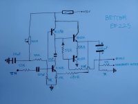
I'm attaching some updates.
The 2k2 resistor is indeed a 22r
The 56k resistor is indeed a 560r
The 3k resistor is indeed a 1k
The schematic is ok. I've spent plenty of time with it. There aren't jumpers nor other components that I'm missing. The 220nf is actually the input capacitor, no doubt. Beyond that cap all belongs to the control stage.
When I touch the 220nf input cap I got hum.
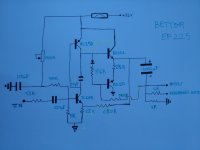
I'm attaching some voltage measures I've done. Base and collector from the 107B make hum. The tests were done with speaker and all pots turned down to 0.
This thing is driving me crazy.
The 2k2 resistor is indeed a 22r
The 56k resistor is indeed a 560r
The 3k resistor is indeed a 1k
The schematic is ok. I've spent plenty of time with it. There aren't jumpers nor other components that I'm missing. The 220nf is actually the input capacitor, no doubt. Beyond that cap all belongs to the control stage.
When I touch the 220nf input cap I got hum.
I'm attaching some voltage measures I've done. Base and collector from the 107B make hum. The tests were done with speaker and all pots turned down to 0.
This thing is driving me crazy.
Attachments

Last edited:
Hum when touched is a sign that the power amplifier is working. If you feed sound from the smartphone's output, you can better assess the condition of your amplifier.
You can install the sound generator application on your smartphone and work like a professional.
Trimmer 500k is used for installation at the output 1/2 from 32 V.
The voltages look normal. The diagram, in my opinion, lacks a resistor between E-B MC-150. I would bet, but it is not necessary.🙂
If you determine that the power amplifier is working properly, look for an error in the pre-amplifier. These can be small electrolytic capacitors, switches, control.
The amplifier is designed for speakers with an impedance of at least 8 ohms (more is better). Otherwise it may distort.
Check what kind of sound comes out of the headphones.(Without speakers)
Last edited:
According to the second image in post 26 there is a 0.47 V difference in the readings across 0.5R (21.57-21.1) meaning the current would be 0.94 A.
If this is a carbon film resistor the value could have gone high.
If this is a carbon film resistor the value could have gone high.
Measure voltage directly on the 0.5 ohm resistor.
Possibly faulty diode, resistor 5,6 or bad connection.
Check the capacitor from the speaker output.
Possibly faulty diode, resistor 5,6 or bad connection.
Check the capacitor from the speaker output.
Last edited:
There's no resistor between E-C MC150. But I will take a closer look.
The sound is bad. It is only acceptable at low volumes. Acceptable although not too good. Once the distortion is high, the sound is unbearable.
With the 500k trimmer at max. I get 17.75v, which is close to the half supply. Maybe with a 1M trimmer I get the half supply...But that can't be like that. There's something wrong.
I'm using 8ohm speakers. The distortion comes from bass frequencies.
I tried it with headphones and it sounds ok 😱 I doesn't distort. I don't understand it...If you look at my schematic, there are two outputs: one with a 47r resistor and the other one without it. Maybe they are reversed? Would that make sense?
BTW. If I don't fix the pots to the chassis with nuts, they make a lot of noise when touched.
I've just measured across the 0.5r resistor. There's like 10mV difference or less when the read is stable. This is a strange resistor, it looks like the threaded part of a screw. The resistors that get very VERY HOT are the 680r and the 5.6r.
Last edited:
680r and 560r may be hot, but 5,6r?
It is necessary to check the MС150 (replacement of PNP, for example BD140).
Only 20 parts 🙂
Try to compare the working and non-working channels (voltages).
It is necessary to check the MС150 (replacement of PNP, for example BD140).
Only 20 parts 🙂
Try to compare the working and non-working channels (voltages).
Last edited:
I replaced the MC150 with no luck.
The 5.6r is right next to the 680r. But yeah, the hot one is the 680r.
Both channels behaves the same.
The 5.6r is right next to the 680r. But yeah, the hot one is the 680r.
Both channels behaves the same.
Note: Feed the signal directly to the output stage to avoid preamp error. - solo tranquilidad🙂
Last edited:
What of the output transistors is either of these running hot. Also what is the (in circuit - power off ) measured resistance of the BD131 emitter resistor (nominally 0.5R) that was asked for.
My thinking is this is likely a 2W carbon film type - the resistance of these is determined by the length of the spiral wound cut having a screw thread appearance.
If the resistance of component has "gone high" due to exposure to heat over the life of the amplifier then level of current passing through BD132 will be reduced and the balance will pass through 680R which is generating an abnormal amount of heat.
I have used 1 Ohm 1Watt resistors in place of fuses in power supplies tests because they are cheaper. When the current is too high these can expire instantly without showing external signs of having done so - that is a somewhat different situation to a slow burn with progressive heat build and smoke with lesser levels of current.
That 0.5r resistor is 1r in circuit. But having into account that my tester leads are 0.5r, we get the correct value. I will upload a picture of that resistor.
I've done some tests.
1) Bypass the switching board completely. It's totally off. The input goes directly to the main audio board. The problem still the same: high voltage and farting distortion on low frequencies.
2) Input signal feed directly to the output stage. I flipped one end of the 3.3k input resistor and remove the power supply to the rest of the board. Now only the output stage of the schematic is feed with voltage. The voltage problem still happens. The distortion is different though. It's more distortion than farting lows.
The thing is as isolated as possible, I don't get it.
Before these tests, when I tried the headphones the audio sounded good without distortion, although the voltage were still bad. Can I try the speaker to the headphones output? I could've swapped them by mistake in the past.
What you have shown in your sketch has an odd look about it. OldDiy showed an image similar in post 20 with component details in the link. That should serve as a guide for comparative purposes with what you have. You may want to change some of your detail
Do you mean to make it look prettier? I'm sure it can be done better, but honestly it's an easy schematic to follow.
If you meant that it might be wrong, well... I don't think so. There are just these components at the output stage. I can assure that. I've checked every connection lots of times. It's possible that I've missed one, but I doubt it. I've checked it many time.
I'm going to draw it again so it can look more like the image you mentioned.
Circuit # 26-2 can work 🙂 Feedback (for DC and AC voltage) is fed from the output to the emitter of the first transistor npn. It controls the base current of the second PNP transistor. He works for EF1. Bootstrap with speaker.
Partially the amplifier works (for headphones). The inability to set the bias of the first transistor so that the output is 1/2. The circuit is sensitive to the Hfe output transistors (the more the better).
Feeling that bd132 does not work 🙁 Is it SE?
Maybe there is a fault in the bias circuit (5.6p and diode). Try the jumper one at a time.
If you connect the speaker through 47 ohms (headphones) you will not get the volume. When zoomed in, there will be distortion.
560r current flows through the speaker (that's right).
The speaker should have a slight voltage of 400 mV.
Last edited:
- Home
- Amplifiers
- Solid State
- Mid 70's amp distorting pretty badly. High crazy base voltages 20v¿?