I moved both the LoopGainProbe.asc and the .asy in the folder where I have my project.
I can import the .asy as is normally done, and run the sim.
But when I try to plot I get this error:
"Unknown current requested: I(Vi)"
How does that work with the subcircuit, is that automatically 'opened' or parsed, or do I need to point to it explicitly somewhere?
I have checked the Tools menu boxes to save subcircuit voltages and currents.
I tried .include LoopGainProbe.asc on my circuit, but that threw an error "Multiple instances of 'Flag'"...
Jan
Can I ask, why do you use the Vnodebuf in your subcircuit? Not that it makes a difference (I checked) but just curious.
Jan
It may be due to some LTSpice-specific issue as it does not seem to work without the additional voltage source. BTW this LTSpice Tian probe was originally created by Frank Wiedmann (see Loop Gain Simulation - Frank Wiedmann).
I moved both the LoopGainProbe.asc and the .asy in the folder where I have my project.
I can import the .asy as is normally done, and run the sim.
But when I try to plot I get this error:
"Unknown current requested: I(Vi)"
How does that work with the subcircuit, is that automatically 'opened' or parsed, or do I need to point to it explicitly somewhere?
I have checked the Tools menu boxes to save subcircuit voltages and currents.
I tried .include LoopGainProbe.asc on my circuit, but that threw an error "Multiple instances of 'Flag'"...
Jan
When you click right mouse button on the probe symbol in the schematic it should show where it looks for the subcircuit schematic.
When you click right mouse button on the probe symbol in the schematic it should show where it looks for the subcircuit schematic.
(Slapping his forehead) Yes of course ...
I(Vi) and V(Ii) are not available as trace. So I need to fix that.
Jan
(Slapping his forehead) Yes of course ...
I(Vi) and V(Ii) are not available as trace. So I need to fix that.
Jan
Jan,
The way you call the voltages and currents for the subcircuit is in Bohrok’s function that you asked about in post 97. The hierarchy of the subcircuit becomes part of the node and component names in the subcircuit.
As far as reversing polarity of the probe sources, the resulting minus signs must cancel in the math. Which explains how the probe works regardless of which side is output and which side is feedback.
After some testing I found the problem in your schematic. On the voltage source you had "AC {-u(prb)}. That should be "AC {u(-prb)}.
Thank you very much, I missed that!
I'll correct it, see how that changes things.
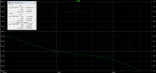
Edit: yes, that fixed the unrealistic curve I saw. It's now pretty much like the datasheet would predict.
Jan
I'll correct it, see how that changes things.
Edit: yes, that fixed the unrealistic curve I saw. It's now pretty much like the datasheet would predict.
Jan
Last edited:
Thanks guys, I have it running now reliably, including the phase and gain margin calculations.
I'll next go and apply it to several designs I am working on.
I may yet come back for more advice 😎
Jan
I'll next go and apply it to several designs I am working on.
I may yet come back for more advice 😎
Jan
Hi everyone. Minek ,in the scheme of the first post, there is an unsuccessful diode limiter. It is necessary to change its circuit, to make it on 4 diodes with an offset from the power supply buses of the op-amp.
Attachments
Last edited:
Maxim, check post #69, diodes D7/D8 do actual clipping control.
D5/D6 don't really prevent clipping, but they do remove some ringing while
clipping happens.
==============
Максим, чек пост №69, диоды D7 / D8 реально контролируют клиппирование.
D5 / D6 на самом деле не предотвращают обрезку, но они удаляют некоторый звон во время происходит отсечение.
D5/D6 don't really prevent clipping, but they do remove some ringing while
clipping happens.
==============
Максим, чек пост №69, диоды D7 / D8 реально контролируют клиппирование.
D5 / D6 на самом деле не предотвращают обрезку, но они удаляют некоторый звон во время происходит отсечение.
No, a simple limiter overloads the oramp output. This more complex limiter is free from this disadvantage. You don't need to use a correction capacitor.
I need to make an amp model. In MS-12
I need to make an amp model. In MS-12
Last edited:
The op-amp output signal is very low - I was unable to make simple limiter between op-amp input/output to work correctly...
=====
Выходной сигнал операционного усилителя очень низкий - мне не удалось сделать простой ограничитель между входом / выходом операционного усилителя, чтобы он работал правильно ...
=====
Выходной сигнал операционного усилителя очень низкий - мне не удалось сделать простой ограничитель между входом / выходом операционного усилителя, чтобы он работал правильно ...
Is it related to clipping?. I don't think so..
I have a resistor in Q1 in this new schematic, but much lower value.
1k was too much. Higher Thd, and less stable.
I have a resistor in Q1 in this new schematic, but much lower value.
1k was too much. Higher Thd, and less stable.
The voltage drop is 1k higher. More amplitude at the Opamp output. Less loop gain. More Thd🙁
I mean the Wiederhold circuit.
I mean the Wiederhold circuit.
Last edited:
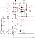
Following Hugh's suggestions, I finally manged to find time to make this design stable (rock solid it is), with very simple compensation.
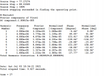
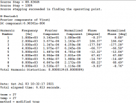
Phase Margin: 66
Gain Margin: 17
SlewRate: over 60V/us
It's also very simple.
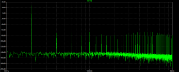
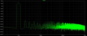
Thd and FFT plots are done for 1kHz and 20kHz
Phase Margin: 66
Gain Margin: 17
SlewRate: over 60V/us
It's also very simple.
Thd and FFT plots are done for 1kHz and 20kHz
Hi Minek,
I reduced the counts part, changed to the Toshiba bipolars and IRFP240 series at the output. With 58mA quiescent it gives you VERY low 1KHz distortion with relative simplicity.
I dropped the shunt fb cap. If you use the 1056 IC it should control the offset very well.
This is a very good way to build a power amp at low cost. Thank you for showing it to us!
Hugh
Attachments
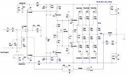
Here is clipping protection added. It clips nicely, and doesn't add to Thd.
By changing Zener voltage, we can choose how close to the rails we want to clip (in this case 10V below rails).
Op-amp is still sticking to its rails for a quick moment. Not sure how to prevent this.
All standard clipping protection circuits added the input/output of the amp, are making Thd number much worse, and they don't really clip nicely...
Perhaps current limiter can be added to the rails of op-amps?
Besides clipping, this amp (asc file from this post) seems like a solid candidate for a build.
I can actually build it by re-purposing one of the PCBs I still have from other 'unusual' amps built last year.
Attachments

Last edited:
- Home
- Amplifiers
- Solid State
- Symmetrical amp clipping behavior - help needed