The halogen, or other incandescent, or other PTC won't work. It has to have an initial high resistance when cold, then low when warm. Then the bias current of your amp will keep the limiter resistance low for recharging your caps.
The inrush current is at it's very highest at the moment the power switch turns on. By the time the limiter warms up to low resistance, the event is over, and you have normal operation and high charging current is available.
In other words, follow Mark's advice.
The inrush current is at it's very highest at the moment the power switch turns on. By the time the limiter warms up to low resistance, the event is over, and you have normal operation and high charging current is available.
In other words, follow Mark's advice.
Hello,
I guess your hearing has been damaged while taking the roof of.
Some amps just work better with bigger caps. But must use CRC or better CLC not just rectifier and a big cap because that will stress the rectifier and transformer.
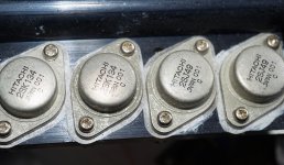
My k135 hitachi which i bought at a reputable company a few decades ago have code 3a1. But that could be another date? Code. They are individually packed in a pink plastic. Maybe my supplier got a box with the code you are looking for.
Greetings,Eduard
I guess your hearing has been damaged while taking the roof of.
Some amps just work better with bigger caps. But must use CRC or better CLC not just rectifier and a big cap because that will stress the rectifier and transformer.
My k135 hitachi which i bought at a reputable company a few decades ago have code 3a1. But that could be another date? Code. They are individually packed in a pink plastic. Maybe my supplier got a box with the code you are looking for.
Greetings,Eduard
150,000uf ? how many watts is your amp ?
I have used a 225WRMS class AB amps with 10,000uf per rail.
I used that on a mobile disco for many years and it nearly took the roof off.
You are right. Ive seen 1200WPCH into 2Ohms PA amplifiers that had 20mF per rail. But they used 5x4700uF for reasons il get to.
What is important is ripple current rating of the capacitors for long life. and good impedance.
If you start using caps the size of soda bottles they actually dont filter that well as low ESL/ESR caps.
I can suggest using PSUD2 to better estimate the peak secondary current available for any of your cap or CRC arrangements. But you need to make the effort to measure PT primary and secondary winding resistances with some accuracy (ie. perhaps aim for a voltage drop and measured current method than a resistance measurement method unless you have a Kelvin probe setup suitable for low resistance measurement).
Also note that the primary winding magnetising inrush current by itself (if it is substantial like for a toroid) will suppress the current capability for the initial charge cycle or two for the capacitors - so you won't see an A + B effect on the mains feed current with respect to tripping a feed cb or fuse.
PSUD2 will allow you to check the diode current capability, and the value/type of fusing you may want to use on the secondary winding.
I want to +1 Mark Johnson's idea to use an NTC thermistor between the first cap bank (smaller one) and the second (much larger one). You can probably use as much resistance as you wish to slow the charging using the thermistors in series (never use them in parallel). Largest inrush will be at turn on when caps are drained and are looking like a short. Thermistors will heat up, then their resistance falls, but as the caps charge up the current flow will diminish and the thermistor resistance will creep back up. Eventually the second bank will be all charged up minus some drop across the thermistors, so you should probably short across them with a relay at that point. Just spitballing most of this, but I have always wondered about how to solve this myself, since I have a boatload of large caps that are begging me to be used en masse! Let us know how it works out.
The best possible (== lots of parts, lots of money) approach is to install a constant current source, a voltage comparator, and a bypass relay. The constant current source charges the ridiculously oversized capacitor bank at a fixed, constant current, sufficiently low that it poses no danger to the rectifiers or to the transformer secondary fuses. When the capacitor bank has charged up to X percent of its final value, the voltage comparator switches logic state. This turns on the bypass relay which shorts out the current source. Let us hope that in steady state, long after inrush is over, the peak of the capacitor charging current-pulses is small enough that it doesn't destroy the rectifiers.
You are right on the mark, i suggest looking at a”hot swap controller” and a Linear mosfet to act as an electronic current limiter.
Its exactly what you describe but in one IC.
Understanding Hot Swap: Example of Hot-Swap Circuit Design Process | Analog Devices
Its exactly what you describe but in one IC.
Understanding Hot Swap: Example of Hot-Swap Circuit Design Process | Analog Devices
Last edited:
Without going to such extremes of capacitance (150,000) I'd take the reasonable, sensible route and use no more than 20,000uF per rail, as is the usual case, if this is a home-based amplifier.
Why complicate matters with all the suggested remedies mentioned?
Besides, using such a huge amount of capacitance isn't going to net anyone anything.
If the OP insists on using these monster cans "for looks", then great, mount them, just for looks, unconnected.
Why complicate matters with all the suggested remedies mentioned?
Besides, using such a huge amount of capacitance isn't going to net anyone anything.
If the OP insists on using these monster cans "for looks", then great, mount them, just for looks, unconnected.
My k135 hitachi which i bought at a reputable company a few decades ago have code 3a1. But that could be another date? Code. They are individually packed in a pink plastic. Maybe my supplier got a box with the code you are looking for.
Greetings,Eduard
I guess the middle letters correspond with classes of gs voltages.
But the numbers, do they have any meaning ?
You are right. Ive seen 1200WPCH into 2Ohms PA amplifiers that had 20mF per rail. But they used 5x4700uF for reasons il get to.
The energy of a cap depends on the square of the voltage.
Maybe that is why pa with high rail voltage not needs large caps. Also most pa are built with low parts quality and simple circuits.
Look at the caps in tube amplifiers... 100 µF
My rails are low, so my caps are big.
I feel a separate thread in the Parts section might be more appropriate to address this, but - AFAIK - those 3 numbers / letters is just the standard Hitachi date code:I guess the middle letters correspond with classes of gs voltages.
But the numbers, do they have any meaning ?
Last digit of the year | Month code | Week of the month
The month codes are: A = Jan, B = Feb, ..., H = Aug, then I is skipped, so J = Sep, ..., M = Dec.
Hence, 3a1 would be the 1st week of January 19x3.
For what it's worth, none of my vintage Hitachi data books mentions any grading / ranking for the 2SJ47-50 / 2SK132-5 parts...
Toshiba data sheets do indeed list grading codes (O, Y, GR) for 2SA1015 (and many other of their transistors).
Hitachi data sheets also list grading codes for many parts, e.g. D, E or F for 2SA872 / 2SC1775, but those are printed as extra letters on the packages - they are not part of the 3-letter date code.
I'm not disputing that graded 2SJ50 / 2SK135 existed (perhaps sold exclusively as pre-sorted replacement parts for specific products?), all I'm saying is that none of the data books I have (1978+) lists grading codes for these, and that the 3-letter code is just a date code...
Which proves my claim that the grading is not part of the date code. ")
As to the actual characteristic denoted by the grade - you're more likely to get answers in the Parts section. I would like to help you, but like I said - none of my vintage Hitachi data books mention any grading for 2SJ47-50 / 2SK132-5...
As to the actual characteristic denoted by the grade - you're more likely to get answers in the Parts section. I would like to help you, but like I said - none of my vintage Hitachi data books mention any grading for 2SJ47-50 / 2SK132-5...
- Status
- This old topic is closed. If you want to reopen this topic, contact a moderator using the "Report Post" button.
- Home
- Amplifiers
- Solid State
- general and specific amplifier building questions