The inrush current is at it's very highest at the moment the power switch turns on. By the time the limiter warms up to low resistance, the event is over, and you have normal operation and high charging current is available.
A 24V 250W lamp has 0.1 ohms in cold condition, and more than 2 ohms when in use.
It would be overload in the first moment and could reach higer resistance.
Perhaps I give it a try, just for knowing.
Which proves my claim that the grading is not part of the date code. 😉

I have a bunch of questions like this and did not want to open 100 new threads.
Maybe "general amplifier building questions" would have been a better title...
 Title changed and thread moved to Solid State.
I want to +1 Mark Johnson's idea to use an NTC thermistor...
I`m uncomfortable with the thermistor as I can not turn off / on as I wish...
The best possible (== lots of parts, lots of money) approach is to install a constant current source, a voltage comparator, and a bypass relay.
That was my plan eventually after everything else is done.
10 seconds slow charge with Mosfet and a bargraph display showing rail status.
Also I`m cosidering to never turn off the amplifer, instead only disable bias of the output stages.


The energy of a cap depends on the square of the voltage.
Maybe that is why pa with high rail voltage not needs large caps. Also most pa are built with low parts quality and simple circuits.
Look at the caps in tube amplifiers... 100 µF
My rails are low, so my caps are big.
The size of rail cap depends on the _impedance_ of the load (and the mains frequency). Nothing to do with rail _voltage_ - a 6V amp for 8ohm load and a 160V amp for 8 ohms both need something like 6800µF rail caps. The load resistance and rail-caps form an RC circuit during the period between mains cycles and you want the time-constant of that RC circuit to be large enough to limit the voltage droop appropriately to some small percentage(*).
With a switch-mode supply you don't need rail caps for anything but stability really as the effective frequency is orders
of magnitude higher and votlage droop is already handling in the supply feedback look itself.
With 4 ohm load you need bigger rail caps than for 8 ohms.
With a valve circuit the typical load impedance seen by the circuit is several k ohms, so that the rail caps can be much smaller (although PSRR is typically poor in valve amps so the rail caps have to limit droop much better than a solid state amp as ripple gets through into the output).
(*) 8 ohms x 0.0068F = 0.05seconds, so the time constant is 5 mains half-cycles, or about 10 times the period for which the rectifiers aren't conducting under heavy load
Last edited:
Just spitballing most of this, but I have always wondered about how to solve this myself, since I have a boatload of large caps that are begging me to be used en masse! Let us know how it works out.
Now I install 3 x MPC74 1 ohm in parallel and hope they not blow.
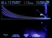
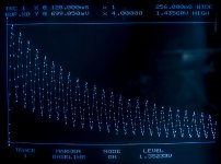
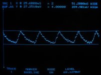
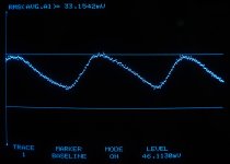
When everything is ok I try to catch the turn on spike with my scope.
With a valve circuit the typical load impedance seen by the circuit is several k ohms, so that the rail caps can be much smaller (although PSRR is typically poor in valve amps so the rail caps have to limit droop much better than a solid state amp as ripple gets through into the output).
Ok, mostly true for tube amps, not all have output transformers, however PA amps are always short of capacitance while high end stuff usually has big bottles. For PA if the rails collapse and the amp clips, who cares...
I prefer a stable supply.
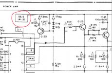
From a Pioneer manual:
22.000 µF per rail for stereo. Rail voltage 55.5V at no signal, 41.5V at rated power.
Attachments
BTW an awful lot of texts make a complete meal of calculating "smoothing" capacitors for amps when all you need is the RC time constant plus the conduction angle of the rectifiers.
I suspect this is due to many power supplies expecting constant current loads (due to having a linear regulator after the smoothing cap). The RC time constant doesn't apply then and you have regulator headroom as well so the calculations look more complicated.
More detailed analysis looks at the effect of the cap size on conduction angle of the rectifiers too, since this affects droop due to transformer winding resistance/losses, as well as the droop-time itself.
I discharged total 125.000µF from 24V with the 250W lamp, put two wires together to close the circuit to see... the spark was very small and the lamp shortly went dark orange.
Imagine what happens when shorting directly 😱
So that could work 🙂
After that I tried to charge CRC 10.000 - 0.33 ohms - 115.000 to 35 V with T4A secundary fuse, it flashed. With T6.3A it is ok.
Adding the lamp, it does not go orange at all. 😕 Perhaps the current is already limited to much by the resistor and the toroid...
Last edited:
There is a short and slight dip in the brightness of my working light when turning on power with CRC. With the lamp in series that is not the case.
Unfortunately the insert loss of the lamp is 4V at 3A.
Unfortunately the insert loss of the lamp is 4V at 3A.
BFnnn - as in B="silicon" F="high frequency low power."? High frequency really means low Cbc in this context I suspect, meaning high slew rate.
- Home
- Amplifiers
- Solid State
- general and specific amplifier building questions