Hello
Looking for all the Mosfet Output Gurus; I'm sure You will know the answer!
Attached is the hand drawn copy of a Well-known Mosfet Band amplifier which was designed here in New Zealand years ago, and is known to be virtually bulletproof.
Because of this, I just went ahead and copied the circuit and produced my own PC boards as I have done other times.
The only change from the original is that I am using Hitachi 2SJ56 and 2SK176 Output devices, which I had a few of. The Original Devices were BUZ901 and BUZ906. I did not need the 400 Watts of the Original circuit, so I am only using 2 Output Devices instead of 8 per channel.
I carefully checked the specifications of these substitute devices to find that they were indeed very similar, before I started construction.
The amp sets up perfectly and is very stable. The Quiescent Current in the output devices is about 4 mV measured across the .22 Ohm Resistors, which is of course 0.0181A or 18 milliamps. The circuit as it is has no way to adjust this value.
The problem the amp has, is that when you apply an Audio Input circuit, the output is quite distorted and the Output Devices immediately start to heat up, even though they are heatsunk to a good sink. Thus far, I have not supplied it with a sine wave input to be able to examine it's output. Maybe I have missed something important, maybe the substitution of Output Devices? I was looking for a simple circuit -- maybe too simple?
No doubt someone will have the answer!
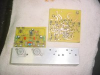
Attachments
Mosfet amp oscillating
I believe that I would add the compensation cap between pin 3 and 6. The output of the opamp is being inverted.
I believe that I would add the compensation cap between pin 3 and 6. The output of the opamp is being inverted.
Hello
Looking for all the Mosfet Output Gurus; I'm sure You will know the answer!
Attached is the hand drawn copy of a Well-known Mosfet Band amplifier which was designed here in New Zealand years ago, and is known to be virtually bulletproof.
Because of this, I just went ahead and copied the circuit and produced my own PC boards as I have done other times.
The only change from the original is that I am using Hitachi 2SJ56 and 2SK176 Output devices, which I had a few of. The Original Devices were BUZ901 and BUZ906. I did not need the 400 Watts of the Original circuit, so I am only using 2 Output Devices instead of 8 per channel.
I carefully checked the specifications of these substitute devices to find that they were indeed very similar, before I started construction.
The amp sets up perfectly and is very stable. The Quiescent Current in the output devices is about 4 mV measured across the .22 Ohm Resistors, which is of course 0.0181A or 18 milliamps. The circuit as it is has no way to adjust this value.
The problem the amp has, is that when you apply an Audio Input circuit, the output is quite distorted and the Output Devices immediately start to heat up, even though they are heatsunk to a good sink. Thus far, I have not supplied it with a sine wave input to be able to examine it's output. Maybe I have missed something important, maybe the substitution of Output Devices? I was looking for a simple circuit -- maybe too simple?
No doubt someone will have the answer!
The quiescent current should be more like 50mA to 150mA range, so the bias needs increasing - the 1k8 bias resistors(*) probable just need a small 1k or 2k2 trimmer in series to allow setting this to a reasonable value.
The circuit needs protection zener+diode across gate-source to protect the gate oxide from catastrophic failure.
The placing of the fuses makes me feel a bit quesy too, fuses drop a lot of voltage when hot, and they run hot well before the rated current. I think they belong in the rails, otherwise the bias point is going to fluctuate a lot with the thermal history of the fuses.
(*) the ones from the rails to the driver transistors that set the gate/source voltage.
Hello
One thing I did was that I suspected Oscillation right away and connected the 'scope but there is no sign of that. The 15 Ohm Resistors don't look as though they have been heating up. While building this, I had found out that the LF357 was a obsolete part, and had considered swapping it out for something like a TL071, but I wanted to get it going as close to the original design as possible for a starting point.
I of course absolutely agree with the idea of Oscillation, So I will closely examine it again for that.
I thought at it would have been obvious on the 'scope, but no, and my 'scope is a
good 150 Mhz Device.
Okay; next question: if I find that it IS Oscillating, what is the correction? Higher Resistances in the Gate Drive Circuits?
Thanks everyone for the help --
Do Members think that this is a Good Circuit? (and the original design did not have fuses in the supply lines).
The opamp + and - ve input pins seems reversed in the schematic. Appears too much or open loop gain from the IC. Check out the 220K / 4.7K feedback loop and polarity on the IC. Also check if the zero offset pot common to be connected to + or - side of the power supply. Vary with opamp. Regards.
Last edited:
Hello
I agree with that; during construction I looked at other Power Amp Circuits which had Opamp front ends and this connection did seem similar; So I think what I will do now is to open up the original Band Amplifier and check every connection to make sure I got it right.
The Offset adjust pot does exactly that, and examining the datasheet for the LF357 it suggests that the Offset pot common should be connected to the Positive Rail.
Thanks again --
Agreed amp is not stable.
the 10p capacitor from pin 2 to 6 could probably be increased 22 or 33p
Also the large 220u capacitors are needed after the zeners.
But the OpAmp also needs smaller .01 or 100n decoupling capacitors placed
very close to the opamp power pins 7 and 4 for stability.
The output devices also need more bias current.
Last edited:
I believe that I would add the compensation cap between pin 3 and 6. The output of the opamp is being inverted.
That would turn it into a kind of Schmitt trigger oscillator. The circuit after the op-amp indeed inverts, but that doesn't change the polarity of the op-amp itself, so the compensation still needs to be between pins 6 and 2.
Hello
Today, I'm going to add some .1uF bypass caps near to the Opamp Power pins, to see if this helps. The Values of the Gate Stopper resistors are directly from the original design, but of course they were meant to suit the original BUZ901/906 pair. All of the Component Values are directly from the original design. The Original Band Amplifier did not have the driver devices heatsunk, so I assumed that there was no need to do so, and they were each driving 4 x Output Devices. Mine is only driving one -- What Value would you suggest for the Output Series Inductor?
Thanks to everyone for the great help!
- Status
- This old topic is closed. If you want to reopen this topic, contact a moderator using the "Report Post" button.
- Home
- Amplifiers
- Solid State
- Why won't this Mosfet Amp Work Properly?