The device differences just mean you need to ensure the time constants are similar and have not gone out of whack with the use of them. Higher capacitances will probably mean more current is needed to charge the gates. I am not an expert in this area so welcome others' comments.
One good thing about the Hitachi Latfets is that the data sheets and symbol say they have built-in gate protection diodes so you don't need to add those....see data sheet.
Coils are a pain and take up a lot of room on PCBs. They are often left to be mounted on the speaker out terminals. Only the Zobel remains on the PCB.
The amp that Minek123 referred to has some similarities to the one you have built, despite using opposite polarities for the output devices and using an extra set of trannies. The characteristics that Minek123 has reported are that it is also rock solid and he has run the sims etc to back that up. You might find some ideas in his schematic that could help make your amp perform better.🙂
Hello
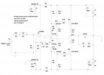
Thanks again for that -- Do You think that this is a Good Design? the Circuit is a direct copy of a New Zealand designed and built Band Amplifier which is well known to be very reliable.... Do You think I would have more luck if I just was to replace the Output Devices with the BUZ901/906 Pair?
Thanks again for that -- Do You think that this is a Good Design? the Circuit is a direct copy of a New Zealand designed and built Band Amplifier which is well known to be very reliable.... Do You think I would have more luck if I just was to replace the Output Devices with the BUZ901/906 Pair?
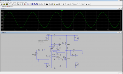
Here is a sim of your amp - using Exicon Latfets, that should be roughly equivalent of Hitachis.
As op-amp I used jfet LT1056.
As is, it runs with 1.8A of idle current.
Thd at 1kHz: 0.02% which is surprisingly low, judging from this schematic, I was expecting worse number.
There is huge current cross-conduction in the output devices - result of huge idle current.
At 1kHz I don't see any obvious oscillations (also consequence of the huge idle current I guess).
At 10 kHz Thd is 0.2%.
Oscillations showing up, but nothing tragic, most likely barely audible..
Not acceptable though for a custom built amp (actually not acceptable for any amp).
I didn't even sim square waves, clipping, or load with capacitance..
My guess is if idle current is lowered, there will be more oscillations.
Was it supposed to be class A amp? That would be the first LatFet A class amp I see.
At full power, output devices will dissipate up to 140W each, obviously an impossible task for single pair.
But maybe if some work is put into this sim, and with some adjustments here and there, it might be workable,
if you already have PCBs, etc... With these LatFets you can build very good performing amp.
Attachments
Last edited:
Hello, Minek123 -- Thanks so much --
This is great information. In the meantime, I have added those .1uF bypass capacitors to the OpAmp Power Pins. I had to increase the Value of the 1.8K resistors (as suggested) to 2K7 in order to boost the Quiescent Current in the output pair to 54 Ma. I'm guessing that maybe it might need to be a bit more than that in the end, but the next thing I intend to do is to load it with 8 Ohms and test run it to see what's what.
In Your Sim, how come the Very High Idle Current? If you are using all the resistor values in the drawing which were the same a copied, is this only a result of using different Output Devices?
I don't know whether the Original design was Class A; it is running with Plus and Minus 64 Volts Supply Rails and was claimed to generate over 400 Watts RMS per channel, but that was using 4 Pairs of Output Devices along with their 8 Gate Stopper resistors.
It's an old design now, probably at least 10 -15 Years, but well known for it's reliability.
And the circuit is simple; that's the main reason I copied it.
>If you are using all the resistor values in the drawing which were the same a copied, is this only a result of using different Output Devices?
Unlikely.. BUZ latfets should be very close to Exicons...
No idea why idle current in the sim is higher. I hope I didn't make any mistakes in the sim, but I guess you verified it already..
Do you have a link to the original amp's schematic?
If your idle current is really 18mA, this may make oscillations more likely, with the signal present.
Idle current should be 40mA or more.
If you increase the value of 1k8 resistors in collectors of the VAS devices this will increase the idle current.
Doubling the resistance, increases idle current 4 times.
Does it oscillate without input signal, but with a load connected?
Last edited:
I see the problem. My sim has a bug: bases of VAS are biased from 64V instead from 15V (after Zeners).
New sim attached. Please check if all is correct.
Idle current too low now (64 uA).
Also, looks like Zener current is too low, 6k8 Zener resistors should have lower value (5k1 for instance).
New sim attached. Please check if all is correct.
Idle current too low now (64 uA).
Also, looks like Zener current is too low, 6k8 Zener resistors should have lower value (5k1 for instance).
Attachments
Yes, Agreed; I increased the Value of those resistors to 2K7, and I now read 54mA Idle Current. the Original Design used those BUZ 901 and 906 Devices, but I am only using one of each Hitachi 2SJ56 and 2SK176, as I had a few already.
I'm just about to check it out connected to an 8 Ohm Load resistor, so I will reply with what I find.
There are No Available Schematics for the Original Amp; the Creator of the design destroyed all of the Service Documents because someone used them to copy and build his own amps which were then sold in opposition!
Thanks for All!
Changing 1k8 collector resistors to 3k, brings idle current to 37mA.
Slightly more oscillations than before, especially at 10kHz.
But again - most likely you won't hear them.
Slightly more oscillations than before, especially at 10kHz.
But again - most likely you won't hear them.
Last edited:
With one pair of output devices, I think the rail voltage should be lowered to 40V - 50V. Doesn't make sense to waste energy 🙂 and take risks of destroying LetFets...
Most likely 40V; even 50V might be too much for one pair...
Most likely 40V; even 50V might be too much for one pair...
Last edited:
I guess try with load first (no signal), and then with signal (but no load).
See if it oscillates.
Assuming you have dummy load. Do not try the speaker 🙂
See if it oscillates.
Assuming you have dummy load. Do not try the speaker 🙂
Oscillations at 10kHz still remain, but not too bad, I'm sure further tweaking is possible.
Gate resistors should be 220/330 Ohm, but overall results with 2200/3300 are not that much worse...
Gate resistors should be 220/330 Ohm, but overall results with 2200/3300 are not that much worse...
Hello
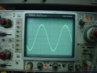
I seem to be getting some much more encouraging results now. No Oscillation when I connected the 8 Ohm Load Resistor. There is some Background Noise, but most of it looks to be Rectified Noise from the Power Supply, which is only temporary and is about 1 M away on the end of leads. Attached is the 'scope trace firstly at 1Kz, and then at 100Khz.
Looks pretty clean to me, and that was at 10 Volts RMS into the 8 Ohm Resistor. I removed the Series Choke to the Speaker, and will wind a new one which I will mount elsewhere. After testing, the IQ rose to about 65 mA which I would expect.
The 22pF capacitor was increased to 33pF, as I did not have 22pF at the time.
Do You think it is a Good Idea to lower the Gate Stopping Resistors to 220/330 Ohms?
I understood that higher values can stop System Oscillation --
Attachments

Re the Question of Supply Voltage:
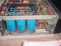
There is another version of this 2SJ56/2SK176 Amp that I have built quite a few times, and those were all, (and still are) running on Plus and Minus 70 Volts. The oldest of which is my Pro Series one, designed by Electronics Australia in 1990. I built this as a 4 Channel Amp to back up my Akai AS980 Quad Receiver, as I used to do DJ Work with it at that time. This has been a Great Amp over time, and has performance figures that are at still better than Perreaux Audio's (In New Zealand) $9000 dollar latest Amp.
If anyone wants the writeup/construction/circuit of it, I will post it to help.
Attached is a shot of the Amp. Really Oversize Power Supply, but, all good.

Interesting that the 8 ohm load resistor improved things so much. The amp should be stable under no load.
I wonder if the Zobel is not using the right cap and resistor values as they seem high. Typically values of 47n up to 220n and resistor values of 2.7 to 10 ohm are used.
I wonder if the Zobel is not using the right cap and resistor values as they seem high. Typically values of 47n up to 220n and resistor values of 2.7 to 10 ohm are used.
This was actually the first time that I had it loaded with a fixed resistor; previous to that it was mounted in the end project, connected to the speakers, when I found that it did not perform properly.
The Zobel Values were taken from the Original Design without change. And the Amp was stable without load today before I connected the load resistor. This was after I increased the Bias Current which before was too low.
Thanks for the help!
The Zobel Values were taken from the Original Design without change. And the Amp was stable without load today before I connected the load resistor. This was after I increased the Bias Current which before was too low.
Thanks for the help!
You could also lower the value for 6k8 Zener resistors (to 5k1).
As is, 15V Zener current is only about 1mA, should be closer to 5mA.
Another thing is the absence of gate protection Zeners.
Not sure if Hitachis have them built in, most likely not.
Exicons have them.
As is, 15V Zener current is only about 1mA, should be closer to 5mA.
Another thing is the absence of gate protection Zeners.
Not sure if Hitachis have them built in, most likely not.
Exicons have them.
- Home
- Amplifiers
- Solid State
- Why won't this Mosfet Amp Work Properly?