I started trying to get this E-MU interface working again back in December so it is great to finally figure out the W10 driver issues.
Thank you for the help!
Driver Booster 8 is freeware and does a wonderful job - searching, installing (all this automatically) and updating drivers without fuzz and very fast. In all the years it only made one mistake!
HF oscillation on an opamp or linear reg almost always manifests itself as a white or pink noise sound when heard over speakers. I don’t quite know the mechanism that causes a 2MHz 1V pk-pk oscillation to sound like this, but that’s my experience. Ditto 4 MHz and 300 kHz oscillation.
Agree. Perhaps it's some kind of slope conversion thing - a good strong signal out-of-band can play merry heck with sum-and-differences alone in any analogue system.
I can also contribute one data point - that by one misplaced small bypass cap across the rails in my preamp when testing some stupidly-wide-bandwidth discrete regs of my own devising - well, it turned the preamp output into a wonderful, low-distortion, 2.1MHz oscillator at 40v pk-pk 😱
That didn't sound like anything at all, but a low-vol hiss of white noise at the speakers.
Mercifully - everything, inc the preamp active stage, survived...
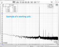
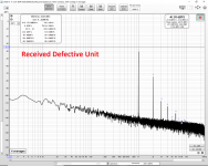
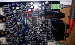
Before I can swap E-MU opamps there is one more things to fix... The first image is a working 1616m DAC output the second image is the 1616m that needs help. I have replaced every supply cap and I have probed the supplies and DAC filter caps everywhere.
The only hint of a problem that I see is that the 4.7 Ohm RC filters on the +/- 12V op-amp supplies (more like +/- 13.5V) show a little hint of being slightly more loaded than the working unit.
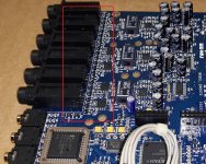
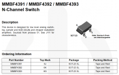
The only theory I have thought of is that the DAC mute circuit is stuck on. The mute circuit seems to consist of 39 Ohm SMD resistors and SOT-23 devices marked "6K" then with a sideways J. Not sure what this device is. Perhaps a "Vishay Siliconix TP0610K" but I am not sure. The third picture shows the SOT-23 of the working unit (circled in red). The 1616m that does not work has a similar but different layout and mute circuit.
Has anyone seen low and distorted output like this on an E-MU 1616 or 1820?
The mute stuck on with 39 Ohms to ground would likely cause the distortion increase from the NJM2068. (And slightly load down the opamp supplies too.)
I don't want to start removing the SOT-23 and/or resistors. I would prefer to better understand and debug it. So far I have not figured out where the control signal comes from. But the third terminal of the SOT-23 mute devices for DACs 1L through 3R are connected to the third terminal of the SOT-23 mute devices next to the headphone output on the other side of the board. So perhaps one global mute circuit. But if that is a "Vishay Siliconix TP0610K" I guess I needed to trace the 2nd terminal/gate to try to find a driver somewhere on the board.
Any guesses on the mute device? Any experience fixing this sort of E-MU 1616/1820 problem? Or possibly similar mute circuit? Any chance an ESD event could take out the entire global mute circuit by shorting the gate of one of the mute devices? (If all the gates are in common and have one driver.)
The only hint of a problem that I see is that the 4.7 Ohm RC filters on the +/- 12V op-amp supplies (more like +/- 13.5V) show a little hint of being slightly more loaded than the working unit.
The only theory I have thought of is that the DAC mute circuit is stuck on. The mute circuit seems to consist of 39 Ohm SMD resistors and SOT-23 devices marked "6K" then with a sideways J. Not sure what this device is. Perhaps a "Vishay Siliconix TP0610K" but I am not sure. The third picture shows the SOT-23 of the working unit (circled in red). The 1616m that does not work has a similar but different layout and mute circuit.
Has anyone seen low and distorted output like this on an E-MU 1616 or 1820?
The mute stuck on with 39 Ohms to ground would likely cause the distortion increase from the NJM2068. (And slightly load down the opamp supplies too.)
I don't want to start removing the SOT-23 and/or resistors. I would prefer to better understand and debug it. So far I have not figured out where the control signal comes from. But the third terminal of the SOT-23 mute devices for DACs 1L through 3R are connected to the third terminal of the SOT-23 mute devices next to the headphone output on the other side of the board. So perhaps one global mute circuit. But if that is a "Vishay Siliconix TP0610K" I guess I needed to trace the 2nd terminal/gate to try to find a driver somewhere on the board.
Any guesses on the mute device? Any experience fixing this sort of E-MU 1616/1820 problem? Or possibly similar mute circuit? Any chance an ESD event could take out the entire global mute circuit by shorting the gate of one of the mute devices? (If all the gates are in common and have one driver.)
Attachments
Attached is a photo of the similar but different mute circuit on the defective E-MU 1616m.
The second photo appears to be the driver circuit for the mute circuit. It has SOT-23 marked 1AM (MMBT3904LT1) and another W2A (PMBT3906). There is also a 104 resistor (100k) and a 105 resistor (1M!).
In the first photo it is possible to see the mute devices with the marking "6K" with the sideways "J". From tracing the circuit I wonder if these are "MMBF4391L, MMBF4392L,MMBF4393L- ON Semiconductor" since the driver is driving the third pin which is common for all the mute devices on the PCB. That would be the gate of the MMBF4391/2/3 JFET.
Any suggestions/hints?
Tomorrow I will try soldering probe wires onto the working and defective mute driver circuits and see if I can determine a difference in the output voltage of the mute driver circuit. This is a pain to debug because it is a sandwich of two PCBs with the components on the inside of the sandwich. You can't power it up without assembling the two halves.
I am not sure yet but I wonder if this circuit is similar to this at ESP: Muting Circuits For Audio
(But with 39 Ohm resistors not 1k Ohm.)
I need to do more work to be sure but I believe the control voltage on the third pin of the defective 1616m is about 0.24 volts which would be consist with the muting being on. (-12V would be muting off.) That is assuming it is like the circuit linked above.
Attachments

Last edited:
TP0610K is a SOT-23 MOSFET with marking code 6K*
If you have a DVM with a diode check function you may be able to see if the device is a possibly JFET, such as MMBF4391L, or not.
If you have a DVM with a diode check function you may be able to see if the device is a possibly JFET, such as MMBF4391L, or not.
Last edited:
I was wondering if I should start an E-MU 1616/1616m/1820/1820m repair thread. I know some other sites have posts about these devices but they don't really have good technical information or repair suggestions beyond the basics of "replace the caps". They don't even mention that the cap problems go beyond the power supply sections and include the caps in the ADC and DAC. Also some of those forums have no photos, which would really help with debugging and repair.
If I start such a thread where in the diyaudio hierarchy of forums do you suggestion I put it?
Anyways, I have fixed the stuck in MUTE problem. If anyone else has low DAC output from these devices here is what I found with my mute circuit:
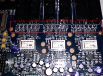
On the attached image I show two test points. One is shown with a red arrow and that is the base of a MMBT3906 PNP in the mute driver circuit before the last resistors that connect to pin 3 of all the mute transistors. (Those resistors are 100k "104" and 1M "105".) The other is shown with a blue arrow and is pin 3 of a mute transistor marked "6K". All of the mute devices have pin 3 connected together across the entire device so you can probe any of them. I soldered 68k 1/4W resistors covered with heat shrink as test points/probes/wires on those two points to debug.
If the 1616 is working then the MMBT3906 base should measure 12 to 13V when the microdock is NOT connected to the PCI card but the microdock is turned on and connected to the 48V supply. That is MUTE ON. If you then connect the microdock to the PCI card it should come out of mute and read -12 to -13V. If you get something like -1.42V then look for blown mute transistors and a blown mute driver. The blown mute transistor can be on any channel and will drag down ALL CHANNELS.
At the third pin of any "6K" mute device on the board (all are connected together) you should measure 0.5V to 0.6V (one Vbe) when the device is in mute. Test this with the microdock NOT connected to the PCI card but with the microdock is turned on and connected to the 48V supply. If you then connect the microdock to the PCI card it should come out of mute and read -12 to -13V. If you get something like -0.24V or 0V to -1V then look for blown mute transistors and a blown mute driver.
Hopefully this will save someone else from two days of debugging.
Just FYI: If you buy these used such as from Ebay be aware that both I bought off Ebay (supposedly fully working but used) were defective. Both had bad capacitors outside of the power supply sections (and inside the power supply). One had dead 5V and 3.3V supplies. The other had a blown mute driver, blown mute transistors and all channels stuck in mute.
With the mute stuck on the DAC output level is about -20 dB down (the NJM2068 driving 39 Ohm SMD resistors to AGND.) So you will hear ok music and might think that it is working. But if you loopback you will see massive 2nd harmonic and levels -20 dB down. The attached "bad example" is -40 dB down because the capacitors are bad and the mute circuit is blown at the same time.
If I start such a thread where in the diyaudio hierarchy of forums do you suggestion I put it?
Anyways, I have fixed the stuck in MUTE problem. If anyone else has low DAC output from these devices here is what I found with my mute circuit:
- The MMBT3904 and MMBT3906 devices that drive the mute devices were damaged. One was shorted, the other looked like a capacitor and another tested ok except for 1.4 mA collector to emitter leakage.
- Those are SOT-23 marked W2 (or W2A) and 1A (or 1AM).
- I replaced those one at a time since I could only detect one failed by DVM probing. Since that changed the behavior but did not fix the problem I removed the other SMD transistors in the mute circuit, measured them in a transistor tester and then replaced them.
- If I repaired this again I would replace all four at one time instead of taking this apart dozens of times over the last two days. Use two soldering irons with tiny fine tips at the same time to remove these SOT-23. Or one with a tiny fine tip and the other with a small curved or bent tip that can contact two SOT-23 pins at the same time. (Anyone know a seller of GOOD long lasting 900M tips? Mine really dissolve in the solder especially when repairing SMD for some reason.)
- I replaced them with SMD MMBT2222 and MMBT2907 devices.
- Even with that it still would not work because the mute devices on the 1L output channel were damaged and dragged down the drive line from the mute driver/level shifter.
- With mute devices damaged on one channel all channels on the device will be muted! They share one driver and if the output is dragged down by one damaged channel all channels will not come out of mute.
- So far I have just desoldered the three "6K" or "6K J" mute devices from channel 1L alone and now all output channels have come out of mute.
- When stuck in mute the outputs will be low and distorted with high 2nd harmonic. The NJM2068 will be trying to drive the 39 Ohm SMD resistors into the mute transistors resulting in high distortion and low output. (See attached imaged.)
On the attached image I show two test points. One is shown with a red arrow and that is the base of a MMBT3906 PNP in the mute driver circuit before the last resistors that connect to pin 3 of all the mute transistors. (Those resistors are 100k "104" and 1M "105".) The other is shown with a blue arrow and is pin 3 of a mute transistor marked "6K". All of the mute devices have pin 3 connected together across the entire device so you can probe any of them. I soldered 68k 1/4W resistors covered with heat shrink as test points/probes/wires on those two points to debug.
If the 1616 is working then the MMBT3906 base should measure 12 to 13V when the microdock is NOT connected to the PCI card but the microdock is turned on and connected to the 48V supply. That is MUTE ON. If you then connect the microdock to the PCI card it should come out of mute and read -12 to -13V. If you get something like -1.42V then look for blown mute transistors and a blown mute driver. The blown mute transistor can be on any channel and will drag down ALL CHANNELS.
At the third pin of any "6K" mute device on the board (all are connected together) you should measure 0.5V to 0.6V (one Vbe) when the device is in mute. Test this with the microdock NOT connected to the PCI card but with the microdock is turned on and connected to the 48V supply. If you then connect the microdock to the PCI card it should come out of mute and read -12 to -13V. If you get something like -0.24V or 0V to -1V then look for blown mute transistors and a blown mute driver.
Hopefully this will save someone else from two days of debugging.
Just FYI: If you buy these used such as from Ebay be aware that both I bought off Ebay (supposedly fully working but used) were defective. Both had bad capacitors outside of the power supply sections (and inside the power supply). One had dead 5V and 3.3V supplies. The other had a blown mute driver, blown mute transistors and all channels stuck in mute.
With the mute stuck on the DAC output level is about -20 dB down (the NJM2068 driving 39 Ohm SMD resistors to AGND.) So you will hear ok music and might think that it is working. But if you loopback you will see massive 2nd harmonic and levels -20 dB down. The attached "bad example" is -40 dB down because the capacitors are bad and the mute circuit is blown at the same time.
Attachments


Last edited:
Too late to edit. There is a mistake: "base of a MMBT3906 PNP" should read "collector of a MMBT3906 PNP". I am sorry I did not catch the mistake soon enough to edit the post.
That collector is the output of the mute driver/level shifter before the 100k and 1M resistors prior to the "6K" muting transistors.
One final comment. I think this might be known flaw for these interfaces because E-MU revised the design/layout and modified the muting circuit. Of my two 1616m microdocks the one that I suspect is the newer one has diodes added presumably for ESD protection at the outputs. They are marked "DI" and "15". They are SOT23 package. So if you are doing debugging and repairs be aware that there are at least two versions/designs/layouts and they are slightly different.
Last edited:
I measured the three removed "6K" marked SOT-23 mute devices from the 1L channel. One was damaged but the other two test as a N-Channel JFET and the pin out matches the MMBF4392 N-Channel JFET Switch. Since the marking code is "6K" for the MMBF4392 that much confirms the device type. [The other possibility for "6K*" was TP0610K MOSFET. That is not the correct device.]
Again only one damaged mute device will leave all channels in mute because the gates are all common and drive by a single level translator and driver.
MMBF4392LT1G can be ordered (at least as of 2021). Perhaps also: MMBFJ112.
Again only one damaged mute device will leave all channels in mute because the gates are all common and drive by a single level translator and driver.
MMBF4392LT1G can be ordered (at least as of 2021). Perhaps also: MMBFJ112.
Attachments
Last edited:
I was wondering if I should start an E-MU 1616/1616m/1820/1820m repair thread. I know some other sites have posts about these devices but they don't really have good technical information or repair suggestions beyond the basics of "replace the caps". They don't even mention that the cap problems go beyond the power supply sections and include the caps in the ADC and DAC. Also some of those forums have no photos, which would really help with debugging and repair.
If I start such a thread where in the diyaudio hierarchy of forums do you suggestion I put it?
Anyways, I have fixed the stuck in MUTE problem. If anyone else has low DAC output from these devices here is what I found with my mute circuit:
How to debug? The following is an example for the 1616 or 1616m which has a 48V external supply allowing you to probe in a known MUTE and known UNMUTE state. With the 1820 you don't have the external power supply and thus easy access to the two states (mute on and mute off) but you can probe and debug what should be the UNMUTE state when connected to the PCI card.
- The MMBT3904 and MMBT3906 devices that drive the mute devices were damaged. One was shorted, the other looked like a capacitor and another tested ok except for 1.4 mA collector to emitter leakage.
- Those are SOT-23 marked W2 (or W2A) and 1A (or 1AM).
- I replaced those one at a time since I could only detect one failed by DVM probing. Since that changed the behavior but did not fix the problem I removed the other SMD transistors in the mute circuit, measured them in a transistor tester and then replaced them.
- If I repaired this again I would replace all four at one time instead of taking this apart dozens of times over the last two days. Use two soldering irons with tiny fine tips at the same time to remove these SOT-23. Or one with a tiny fine tip and the other with a small curved or bent tip that can contact two SOT-23 pins at the same time. (Anyone know a seller of GOOD long lasting 900M tips? Mine really dissolve in the solder especially when repairing SMD for some reason.)
- I replaced them with SMD MMBT2222 and MMBT2907 devices.
- Even with that it still would not work because the mute devices on the 1L output channel were damaged and dragged down the drive line from the mute driver/level shifter.
- With mute devices damaged on one channel all channels on the device will be muted! They share one driver and if the output is dragged down by one damaged channel all channels will not come out of mute.
- So far I have just desoldered the three "6K" or "6K J" mute devices from channel 1L alone and now all output channels have come out of mute.
- When stuck in mute the outputs will be low and distorted with high 2nd harmonic. The NJM2068 will be trying to drive the 39 Ohm SMD resistors into the mute transistors resulting in high distortion and low output. (See attached imaged.)
On the attached image I show two test points. One is shown with a red arrow and that is the base of a MMBT3906 PNP in the mute driver circuit before the last resistors that connect to pin 3 of all the mute transistors. (Those resistors are 100k "104" and 1M "105".) The other is shown with a blue arrow and is pin 3 of a mute transistor marked "6K". All of the mute devices have pin 3 connected together across the entire device so you can probe any of them. I soldered 68k 1/4W resistors covered with heat shrink as test points/probes/wires on those two points to debug.
If the 1616 is working then the MMBT3906 base should measure 12 to 13V when the microdock is NOT connected to the PCI card but the microdock is turned on and connected to the 48V supply. That is MUTE ON. If you then connect the microdock to the PCI card it should come out of mute and read -12 to -13V. If you get something like -1.42V then look for blown mute transistors and a blown mute driver. The blown mute transistor can be on any channel and will drag down ALL CHANNELS.
At the third pin of any "6K" mute device on the board (all are connected together) you should measure 0.5V to 0.6V (one Vbe) when the device is in mute. Test this with the microdock NOT connected to the PCI card but with the microdock is turned on and connected to the 48V supply. If you then connect the microdock to the PCI card it should come out of mute and read -12 to -13V. If you get something like -0.24V or 0V to -1V then look for blown mute transistors and a blown mute driver.
Hopefully this will save someone else from two days of debugging.
Just FYI: If you buy these used such as from Ebay be aware that both I bought off Ebay (supposedly fully working but used) were defective. Both had bad capacitors outside of the power supply sections (and inside the power supply). One had dead 5V and 3.3V supplies. The other had a blown mute driver, blown mute transistors and all channels stuck in mute.
With the mute stuck on the DAC output level is about -20 dB down (the NJM2068 driving 39 Ohm SMD resistors to AGND.) So you will hear ok music and might think that it is working. But if you loopback you will see massive 2nd harmonic and levels -20 dB down. The attached "bad example" is -40 dB down because the capacitors are bad and the mute circuit is blown at the same time.
Fantastic work on this, bookmarked for future reference (hope I never need it...). BTW, what software are you using for the measurement?
Also, if you're a guitarist and doing pedal builds, the NJM2068 is a good candidate for anything needing a dual imo...not so much for ADC/DAC duty imo though despite decent charts.
Last edited:
I am using REW. (REW - Room EQ Wizard Room Acoustics Software. I am using the latest beta.) I just found out about REW a few months ago and I think it is great. There is a thread on DIY Audio about using REW for distortion measurements.
Howto - Distortion Measurements with REW
I have also measured my speaker impedance with REW. (And discovered that those "8 Ohm" speakers are actually 4 Ohm. For a couple of my project amplifiers that really mattered.)
If I remove the NJM2068 cleanly enough I will put them aside for possible future reuse. I have not built a guitar pedal in quite sometime. But I do need to repair an EMG active 2-band EQ that died in my bass. (It was like that when I bought the bass used, so I don't know how it failed.) Unless a cap shorted on the little PCB it looks like the Linear Technology low current opamp died.
One odd thing about the E-MU mute circuit is that measured the removed "6K" marked SMT mute devices and the ones that still function test as N JFET on my M328 transistor tester. So I am pretty sure they are N JFET. But on another site some claimed success in replacing them with a MOSFET with the "6K*" mark:
Badcaps Forums - View Single Post - EMU 1820M not working properly
Last edited:
I have REW but had never used it for this but found the functionality right before you posted, thanks for the additional details. I used REW to measure impedance curves on my cabs and a reactive load box I just built, an invaluable piece of software for that, and now I discover from you it does spectrum too!
After what you posted I decided I better scrutinize my latest 1820m before diving in...
After what you posted I decided I better scrutinize my latest 1820m before diving in...
Both 1616m had bad caps outside of the power supply section. However one was really bad and almost every cap (about 80%) were toast. The other (outside of the power supply) was still functional but in some areas degraded.
So I think it depends on how many hours use and how hot it got. The 1616 and 1820 are two pieces of gear never to put in a soft rack case...
So I think it depends on how many hours use and how hot it got. The 1616 and 1820 are two pieces of gear never to put in a soft rack case...
If I remove the NJM2068 cleanly enough I will put them aside for possible future reuse.
I've had good success by bending a long slender copper tip on one of my 15W soldering irons at a 90 degree angle and then filing it into a thin flat extension that can contact all four pins on one side of the opamp simultaneously. I use a thin jewelers screwdriver to gently pry up the opamp just enough to get the pins off the contact pads and then it comes right off when contacting the other side. Very fast and haven't lost any opamps. There may be better ways but this has worked for me.
Both 1616m had bad caps outside of the power supply section. However one was really bad and almost every cap (about 80%) were toast. The other (outside of the power supply) was still functional but in some areas degraded.
So I think it depends on how many hours use and how hot it got. The 1616 and 1820 are two pieces of gear never to put in a soft rack case...
Speaking of high hours and heat, I just did spectrums for both of my 1820m and the original one with the LM4562 that runs hot has degraded quite a bit since I first did it. The latest one measures as new, so good news there. All to say I cannot recommend 4562 for this application...
Since I'm now recapping two of these, what did your research show to be good for in the signal path? I used Panasonic FM for power and they've held up well.
Last edited:
I tried Tk Audio, Elna RA3 and Panasonic "M" series for the DAC blocks without a consistent measured difference. The best channels had the Tk installed in the first round experiment matrix so I replaced all with Tk in the second round of the experiment. But where I replaced RA3 and M with the Tk (in the second round of the experiment) I can't say that it improved. The best channels might be better more due to the opamps or some other channel to channel variation source. I don't know the cause yet.
For the DAC and ADC FILT/FILT+ caps I used Nichicon VR. I also tried Panasonic SEPC (OS-CON, 6SEPC560MW.) Again I did an experiment with the different channels and the best channels had the VR installed. So I pulled the SEPC/OS-CON and installed VR in the SEPC/OS-CON spots in the second round of the experiment. But again those channels did not improve so the channel to channel variations appear to be coming from another source.
I used NXA low ESR 105 degree caps for the power supply. (1000uF 25V.)
I plan to try others later including freshly ordered Panasonic FM, Nichicon UES (the green bipolars) and Rubycon ZLH.
I like the NXA and ZLH since they are likely to last longer. (High endurance and temperature ratings. Both the E-MU 1820 and 1616 are designed like little ovens.)
In addition one dead 1616m arrived with ELXZ6R3ELL471MF15D United Chemi-Con (UCC) low impedance caps installed as replacements for the ADC FILT caps on one board (but not the other board, not for the mic input ADC). I might get more of those LXZ series 6.3x15mm caps and try them in the last experiment matrix. They are 105 degree C caps, low impedance and the case size fits for the ADC FILT caps. I might also try solid polymer again simply for lifetime/endurance reasons at these temperatures.
I would like high endurance and temperature ratings, especially near the power supply and the hot ADC chips. The AKM ADC gets pretty warm and they are packed in side by side.
Last edited:
The best channels might be better more due to the opamps or some other channel to channel variation source. I don't know the cause yet...
...I would like high endurance and temperature ratings, especially near the power supply and the hot ADC chips. The AKM ADC gets pretty warm and they are packed in side by side.
I noticed in my 1820m that even when new the channels all measured a bit different and after mods the "good" and "less good" were always the same channels.
Ditto the high endurance/temp, I'll select accordingly after seeing how this first one has degraded. Yet to determine if its ADC or DAC or both that degraded, will post once I determine. Hopefully new caps and cooler running opamps restores it.
They do seem to come back to life. I have removed the 5V SMPS caps and measured zero capacitance remaining yet with new caps installed they come back to life. So fortunately nothing damaged. I can't imagine that a high amplitude unfiltered square wave is good for anything, but they seem to survive.
I would be curious to know which caps went on yours and what the degradation looks like. If the degradation is in output amplitude then look at the pairs of 47uF/16V 6.3mm caps (blocks) on the CS4398 DACs. If/when those are ok but if you see distortion degradation (especially if pronounced at lower frequencies) then look at the FILT caps. (470uF 6.3V on the AKM ADC. After the ADC FILT caps then look at the 100uF 25V FILT caps on the CS4398 DACs.)
Those are the ones that I saw the greatest pre to post replacement improvements. I also ended up changing all the electrolytics except the non-polar RN series in the mic preamps. I didn't have replacements for those and so far those seem to work well after everything else was replaced.
Good luck!
Edit: First (before the above) I suggest you probe all the power supplies first. [Did you replace all supply caps or just select ones such as the 5V supply? What about the +/-12V? I say that because one of the used ones I bought had dead power sections where some sections had original bad caps still yet other supply sections had replaced caps.] Also check your PCI card for the 1820m. The same bad cap brands/series are on that PCI card including the SMPS on the PCI card. You can see them next to the yellow SMPS transformer on the PCI card. Actually every electrolytic on that PCI card is a "bad cap" brand/series... [If a 1616 owner reads this then your PCI card is different and lacks the SMPS on the PCI card, which is why you can not mix 1616 and 1820 PCI card versions. Also a PCI card for the 1616 does not have the firewire port.]
Last edited:
I don't know if anyone else has noticed this but the first 1616m was super easy to desolder. The second 1616m and a 1820m seem to be assembled with perhaps a different type of solder and are much harder to desolder. On the first 1616m the caps often just fell out when both pins were heated. (You can see the same thing with the 1820 that someone repaired on the Youtube video.) Also on the first one the leads were straight. On the second 1616m the leads are twisted and it also takes a fair amount of added new solder to get the old caps out.
One 1616m was assembled in Malaysia and the other 1616m was assembled in China. Also the PCB are different revision. There are circuit differences in the mute circuit, for example.
One 1616m was assembled in Malaysia and the other 1616m was assembled in China. Also the PCB are different revision. There are circuit differences in the mute circuit, for example.
Last edited:
I would be curious to know which caps went on yours and what the degradation looks like...
I'm seeing increased distortion (.004) and noise figures (-87) , no problem with output level.
I pulled my old one apart and noticed I left I/O 4 stock, I/O 3 has 4562 on DAC and 2068 on ADC, I/O 1,2 have 4562 on ADC and DAC, and they all measure poorly at this point (clearly I ran short of opamps and forgot all about it) The newer 1820m measures much better but a few channels are beginning to show degradation in distortion and noise figures. So both are getting full recaps. The 4562 are coming out of the first one to help get the heat down. And the PCI cards and my 1212 daughter card are going to get recapped as well. What a pain, but hopefully I can get another 6-7 years out of them.
Actually the quiescent currents of LM4562 and OPA1656 are similar. In LM4562 the 10mA quiescent current is for 2 channels as in OPA1656 3.9mA is for one channel only. NJM2068 is 5mA for 2 channels.
- Home
- Amplifiers
- Solid State
- Choosing of best sounding OP AMPs for the lowest possible THD+N -really the best Way?