.MODEL TTC004B_BJT NPN( LEVEL=1 TNOM=25 IS=1.374e-013 BF=137.2 NF=1 VAF=11.95 IKF=0.5057 ISE=8.098e-013 NE=1.8 BR=35.11 NR=1 VAR=1000 IKR=10 ISC=1.916e-011 NC=1.5 NK=0.55 RE=0.115 RB=0.885 RC=0.0709 CJE=5.78E-011 VJE=0.75 MJE=0.33 CJC=2.89E-011 VJC=0.75 MJC=0.33 FC=0.5 TF=1.545E-009 XTF=1 VTF=1 ITF=1 PTF=0 TR=0 EG=1.11 XTB=1.4 XTI=6.467)
.MODEL TTA004B_BJT PNP( LEVEL=1 TNOM=25 IS=7.5e-014 BF=190 IKF=0.47 ISE=5e-011 NE=2.4 NK=0.63 XTB=1 XTI=2 TRC1=0.003 NF=1 VAF=6.8 VAR=50 BR=6 IKR=5 ISC=1.0e-21 NR=1.015 NC=1 RB=4 RC=0.125 RE=0.05 CJC=4.09E-011 MJC=0.33 VJC=0.75 CJE=1e-11 MJE=0.33 VJE=0.75 EG=1.11 TR=1E-009 TF=1.59E-009)
Sajti
.MODEL TTA004B_BJT PNP( LEVEL=1 TNOM=25 IS=7.5e-014 BF=190 IKF=0.47 ISE=5e-011 NE=2.4 NK=0.63 XTB=1 XTI=2 TRC1=0.003 NF=1 VAF=6.8 VAR=50 BR=6 IKR=5 ISC=1.0e-21 NR=1.015 NC=1 RB=4 RC=0.125 RE=0.05 CJC=4.09E-011 MJC=0.33 VJC=0.75 CJE=1e-11 MJE=0.33 VJE=0.75 EG=1.11 TR=1E-009 TF=1.59E-009)
Sajti
.MODEL TTC011B_BJT NPN( LEVEL=1 IS=5e-013 BF=120 NF=1 VAF=18 IKF=2.2 ISE=1.8e-013 NE=1.3 BR=20 NR=1 VAR=10 IKR=0.005 ISC=1.5e-013 NC=1 NK=0.8 RE=0.08 RB=1.5 RC=0.08 CJE=8e-010 VJE=0.75 MJE=0.33 CJC=4.8156e-011 VJC=0.75 MJC=0.33 FC=0.5 TF=1.2e-009 XTF=10 VTF=2.8 ITF=1 PTF=0 TR=500E-09 EG=1.11 XTB=1.2 XTI=7 TRC1=0 TNOM=25)
.MODEL TTA006B_BJT PNP( LEVEL=1 IS=8e-013 BF=235 NF=1 VAF=40 IKF=0.85 ISE=6.5e-013 NE=1.3 BR=3 NR=1.01 VAR=5 IKR=10 ISC=1e-011 NC=1.3 NK=0.5 RE=0.1 RB=0.4 RC=0.18 CJE=5e-010 VJE=0.75 MJE=0.33 CJC=7.22e-011 VJC=0.75 MJC=0.33 FC=0.5 TF=1.8e-009 XTF=10 VTF=3 ITF=1 PTF=0 TR=10E-09 EG=1.11 XTB=1.9 XTI=3.5 TRC1=0 TNOM=25)
Sajti
Since my last update, I've done a couple of days of after-work research, re-drawing of schematics, and re-simulation.
My KSA1220 driver showed quasi-saturation problems (maybe real, maybe just a bad model), which lead me to research the KSA1220. I discovered ON is not going to make it anymore. That's a real problem, because there's not really a replacement with such an FT and SOA. To paraphrase Gandalf: "All we have to decide is what to do with the *transistors* that are given us."
I looked at the TTC/TTA devices suggested by sajti. They are a little slower than the KSC2690/KSA1220, but still very fast. Their SOA is not nearly as robust as the 2690/1220, and that's the problem. I would have to use at least 2 in parallel to be inside the SOA. I'd rather use the KSC3503/KSA1381 as drivers. Originally, I had (slow) MJE15032/3 drivers, and I replaced each of them with three 3503/1381, and saw good speed of my output stage. the 2690/1220 showed similar speed.
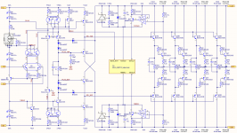
So, last night, I redrew my schematics with 4 KSC3503, each driving a single MJW0281, and 4 KSA1381, each driving a single MJW0302. Drving each output transistor individually let me delete the Zoebel networks and bypasses I had around each output transistor. Frankly, I recommend this. The output stage is now significantly faster.
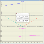
I resimulated DC transfer functions, and open-loop gain.
The DC gain is about as high as before, but the asymmetry is now more pronounced. Even at 0V DC out, there is a slant to the gain. I expect this means there will be an increase in 2nd harmonic. Looks like there is an NPN/PNP asymmetry of beta causing an asymmetric load on the FC output. Bias of the output transistors was kept the same. The wing-spread diagram of with the new drivers actually looks slightly better.
The loop UGF frequency (with CL gain = 20) went up from 3 MHz to 5 MHz, simply due to the replacement of the drivers.
My KSA1220 driver showed quasi-saturation problems (maybe real, maybe just a bad model), which lead me to research the KSA1220. I discovered ON is not going to make it anymore. That's a real problem, because there's not really a replacement with such an FT and SOA. To paraphrase Gandalf: "All we have to decide is what to do with the *transistors* that are given us."
I looked at the TTC/TTA devices suggested by sajti. They are a little slower than the KSC2690/KSA1220, but still very fast. Their SOA is not nearly as robust as the 2690/1220, and that's the problem. I would have to use at least 2 in parallel to be inside the SOA. I'd rather use the KSC3503/KSA1381 as drivers. Originally, I had (slow) MJE15032/3 drivers, and I replaced each of them with three 3503/1381, and saw good speed of my output stage. the 2690/1220 showed similar speed.
So, last night, I redrew my schematics with 4 KSC3503, each driving a single MJW0281, and 4 KSA1381, each driving a single MJW0302. Drving each output transistor individually let me delete the Zoebel networks and bypasses I had around each output transistor. Frankly, I recommend this. The output stage is now significantly faster.
I resimulated DC transfer functions, and open-loop gain.
The DC gain is about as high as before, but the asymmetry is now more pronounced. Even at 0V DC out, there is a slant to the gain. I expect this means there will be an increase in 2nd harmonic. Looks like there is an NPN/PNP asymmetry of beta causing an asymmetric load on the FC output. Bias of the output transistors was kept the same. The wing-spread diagram of with the new drivers actually looks slightly better.
The loop UGF frequency (with CL gain = 20) went up from 3 MHz to 5 MHz, simply due to the replacement of the drivers.
Attachments
More sim results, comparing to the previous version.
I revised the CL test bench slightly, with 3.9pF in parallel with the feedback resistor. It boosts the phase margin a bit to do that.
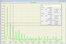
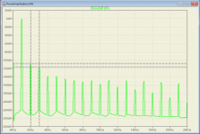
I redid the THD vs frequency & power chart, and a couple of FFTs--at 1kHz, 1W and 100W. Baseline THD is higher for the revision. FFT shows this is due to a 12 dB increase in the 2nd harmonic, even while the 3rd -- 5th harmonics went down. (See plots in post #28 for comparison) At 100W and 200W, the harmonic levels are much closer to the first simulations, which makes sense. The broad shape of the transfer curve is similar.
THD at the highest frequencies is lower. That also makes sense because there is 67% more gain available for error correction, due to the loop UGBW increasing from 3 to 5 MHz.
I revised the CL test bench slightly, with 3.9pF in parallel with the feedback resistor. It boosts the phase margin a bit to do that.
I redid the THD vs frequency & power chart, and a couple of FFTs--at 1kHz, 1W and 100W. Baseline THD is higher for the revision. FFT shows this is due to a 12 dB increase in the 2nd harmonic, even while the 3rd -- 5th harmonics went down. (See plots in post #28 for comparison) At 100W and 200W, the harmonic levels are much closer to the first simulations, which makes sense. The broad shape of the transfer curve is similar.
THD at the highest frequencies is lower. That also makes sense because there is 67% more gain available for error correction, due to the loop UGBW increasing from 3 to 5 MHz.
Attachments
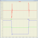
And, I'm clipping the amplifier, again. Anomalous behavior is gone, and the clipping is more symmetric. Again, this might just be due to models that need quasi-sat added.
Attachments
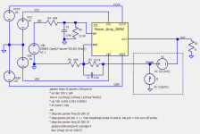
Now, I'm making noise. LTspice says V(onoise) is 99.1 nV/rtHz. Over the audio band, that is 14.01 uV rms of white noise.
The noise is mostly due to the 600 ohm resistance on each input. Within the amplifier, the dominant contributors are the input pair (of course), distantly followed by the current sources/mirrors Q6 and Q7
Source_____Noise (nV/rtHz)
Onoise_____99.1
R=604_____63.4, each
R=12.1K___14.2, each
Q3 inp_____19.5, each
PNP src.____6.2, 6.0
NPN mir____5.2, 4.0
No significant noise from the tail current or the cascode transistors.
Attachments
Last edited:
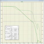
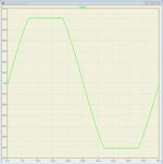
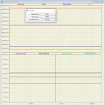
Slew Rate and small sig. square wave response
20 kHz square wave, 80 Vpp, 10% to 90%
Negative Slew rate.
SR- = 2 * 32.02 /(25.798u - 25.117u) = 94.0 V/us
Positive Slew Rate
SR+ = 2 * 31.99 /(50.790u - 50.110u) = 94.1 V/us
Theory predicts SR = Itail/Ccomp = 4mA / 39pF =102 V/us.
The faster driver stage let me drop Ccomp from 62pF to 39pF.
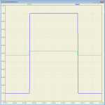
Also, here's a small-signal square wave response. Same input, but 1/40th the amplitude.
20 kHz square wave, 80 Vpp, 10% to 90%
Negative Slew rate.
SR- = 2 * 32.02 /(25.798u - 25.117u) = 94.0 V/us
Positive Slew Rate
SR+ = 2 * 31.99 /(50.790u - 50.110u) = 94.1 V/us
Theory predicts SR = Itail/Ccomp = 4mA / 39pF =102 V/us.
The faster driver stage let me drop Ccomp from 62pF to 39pF.
Also, here's a small-signal square wave response. Same input, but 1/40th the amplitude.
Attachments
@Russel
I have found some time to make simulations and I'm sorry for always comparing your Amp with the FC-100. But I guess the FC100 is the DIY Folded Cascode Audio Reference Amp. Your Amp compares really good.
Something was fishy in my latest plots. Don't know what happen.
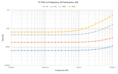
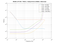
However please find some THD figures 20-200kHz. I havent included your latest changes. First I have to rebuild the complete Amp in Ltspice. Maybee this weekend. I also want to include IMD. I altered your Simulation parameter but at the end the system put out the same data. The purpose of it is are my external Simulation calling skripts.
Btw. The FC-100 shows a strange THD behavior for under 1khz.
Cheers
I have found some time to make simulations and I'm sorry for always comparing your Amp with the FC-100. But I guess the FC100 is the DIY Folded Cascode Audio Reference Amp. Your Amp compares really good.
Something was fishy in my latest plots. Don't know what happen.
However please find some THD figures 20-200kHz. I havent included your latest changes. First I have to rebuild the complete Amp in Ltspice. Maybee this weekend. I also want to include IMD. I altered your Simulation parameter but at the end the system put out the same data. The purpose of it is are my external Simulation calling skripts.
Btw. The FC-100 shows a strange THD behavior for under 1khz.
Cheers
Attachments
Yer data is backwards.
Hi WatrixR,
There is, indeed, something fishy about your THD plot of Mihai's amp. I'm pretty sure you have the data series backwards for the FC-100.
Mihai's amplifier topology is almost identical to mine, including the basic gain-bandwidth mechanisms. The differences are his JFET input and his CFP output. There is no way the FC-100 can go to 200 kHz with constant THD v. Freq. Likewise, there is no way the THD on the FC-100 is going to get worse at frequencies below 1kHz.
I don't really understand why you plot THD to 200 kHz. Harmonics above 20 kHz are inaudible, and IMD above 20 kHz is unimportant, because audio stops at 20 kHz. Even a full-power twin-tone IMD with 19 and 20 kHz is kind of dumb, because full power at 19 kHz never happens off the test bench. Even then, it's the amplifier's linearity at 1 kHz that determines the magnitude of the IMD artifact, not the linearity at 19/20 kHz.
The FC100 has a substantially higher slew rate than the RK200, due to his 8.25mA bias current, and smaller Ccomp values. It looks like at 100W, the RK200 runs out of slew rate at about 60 kHz. The latest schematics of the RK200 reduce Ccomp from 62pF to 39pF, so SR increases inversely, from 59 V/us to 94 V/us.
You know you can just make a symbol in LTspice for my amplifier, and then use my latest netlists without having to redraw? You will still have access to all voltages and device currents for plotting.
Hi,
yes, I know 200khz is absolutely inaudiblle especially the harmonics. Just want to se how it goes beyond 20 khz -and since it is a logarithmic plot it was the natural extention to add one decade on it. Maybe some Bats will enjoy that") but source has to be able to provide it ....anyway this is just for technical curiosity.
but source has to be able to provide it ....anyway this is just for technical curiosity.
Netlist - I did that. Otherwise I wouldn't have the 200khz of your Amp data. I just want experiment with the circuit.
Thats why I dont ḱnow why the THD of the FC-100 is so strange at the beginning. Dispite direct newton itteration for DC operation point is disabled in the command directive.
Solver Settings / tolerance are almost exactly the same. So my settings do work fine for your amp as i get the same values as you.
My settings will result in 20 fourier components of the harmonics. Log will be parsed by an external script which also sets the new base frequency for THD analysis. and starts the process again. THD is just the euclidian norm over the normalised fourier components x100. Calculted by the skript but as said works fine for your amp.
Im using this script to sweep through different values for caps, resistors etc. I want to rebuild the amp completely in LTspice because it makes it easier for me to experiment with it and the scripts.
I have a physics backround but my analog design knowledge is only slightly above the lvl which I have learnd at university.Hence, screw around with it to gain knowledge
yes, I know 200khz is absolutely inaudiblle especially the harmonics. Just want to se how it goes beyond 20 khz -and since it is a logarithmic plot it was the natural extention to add one decade on it. Maybe some Bats will enjoy that
but source has to be able to provide it ....anyway this is just for technical curiosity. Netlist - I did that. Otherwise I wouldn't have the 200khz of your Amp data. I just want experiment with the circuit.
Thats why I dont ḱnow why the THD of the FC-100 is so strange at the beginning. Dispite direct newton itteration for DC operation point is disabled in the command directive.
Solver Settings / tolerance are almost exactly the same. So my settings do work fine for your amp as i get the same values as you.
My settings will result in 20 fourier components of the harmonics. Log will be parsed by an external script which also sets the new base frequency for THD analysis. and starts the process again. THD is just the euclidian norm over the normalised fourier components x100. Calculted by the skript but as said works fine for your amp.
Im using this script to sweep through different values for caps, resistors etc. I want to rebuild the amp completely in LTspice because it makes it easier for me to experiment with it and the scripts.
I have a physics backround but my analog design knowledge is only slightly above the lvl which I have learnd at university.Hence, screw around with it to gain knowledge
Last edited:
I'm more concerned about Vbe matching.
I found it not very hard to match, with same polarity devices. Of course npn/pnp is almost impossible. What was interesting, that matching is easier if You order samples from different vendors.
Sajti
- Home
- Amplifiers
- Solid State
- RK-Auto200W Amplifer