Hi guys,
i am new in this forum, hopefully you can assist me...
I have a Mark Levinson No 335, few weeks ago one channel had distortion and not working correctly.
I decided to inspect it and at the same time to perform the recommended from Mark Levinson upgrades, as well as a re-cap with CDE DCMC caps.
During inspection, i found out that the problematic channel has no bias at the power transistors. And it is not possible to adjust it from the relative potentiometer.
At the same time i found out that the -REG voltage is lower than the +REG (max. 102-103 V DC, instead of 115 V, while the +REG can be adjusted normally at +115 V DC).
The strange thing is that when i try to adjust it, i can not go higher than 102-103 Volts and when i keep turning the potentiometer the voltage drops again. In other words, the max voltage of -102/103 V achieved when the pot is in the middle position, turning it to both ends the voltage is reduced....!
The -PRE_REG voltage can be normally adjusted at 2,1 Volts.
I have performed all recommended from Mark Levinson upgrades, even more than these.
Optically everything looks fine .
.
Had anyone a similar problem ?
If yes, maybe you can advise what I should check?
Any assistance would be highly appreciated! Thank you in advance.
Theodore
i am new in this forum, hopefully you can assist me...
I have a Mark Levinson No 335, few weeks ago one channel had distortion and not working correctly.
I decided to inspect it and at the same time to perform the recommended from Mark Levinson upgrades, as well as a re-cap with CDE DCMC caps.
During inspection, i found out that the problematic channel has no bias at the power transistors. And it is not possible to adjust it from the relative potentiometer.
At the same time i found out that the -REG voltage is lower than the +REG (max. 102-103 V DC, instead of 115 V, while the +REG can be adjusted normally at +115 V DC).
The strange thing is that when i try to adjust it, i can not go higher than 102-103 Volts and when i keep turning the potentiometer the voltage drops again. In other words, the max voltage of -102/103 V achieved when the pot is in the middle position, turning it to both ends the voltage is reduced....!
The -PRE_REG voltage can be normally adjusted at 2,1 Volts.
I have performed all recommended from Mark Levinson upgrades, even more than these.
Optically everything looks fine
.Had anyone a similar problem ?
If yes, maybe you can advise what I should check?
Any assistance would be highly appreciated! Thank you in advance.
Theodore
Hi Theodore,Hi guys,
i am new in this forum, hopefully you can assist me...
I have a Mark Levinson No 335, few weeks ago one channel had distortion and not working correctly.
I decided to inspect it and at the same time to perform the recommended from Mark Levinson upgrades, as well as a re-cap with CDE DCMC caps.
During inspection, i found out that the problematic channel has no bias at the power transistors. And it is not possible to adjust it from the relative potentiometer.
At the same time i found out that the -REG voltage is lower than the +REG (max. 102-103 V DC, instead of 115 V, while the +REG can be adjusted normally at +115 V DC).
The strange thing is that when i try to adjust it, i can not go higher than 102-103 Volts and when i keep turning the potentiometer the voltage drops again. In other words, the max voltage of -102/103 V achieved when the pot is in the middle position, turning it to both ends the voltage is reduced....!
Theodore
This is exactly the problem that you get when Vreg+ and Vreg- are not the same .
Look here for an explanation why.
Mark Levinson No.27 amplifier,,,NEED HELP
Hans
Hi there,
thank you for your quick reply... i just saw them (being busy searching with amp)...
Mooly: few photos of what i mean. if you need more or other infos, just let me know.
Hans: You seem expert on Mark Levinson products here. i read your recommended post (all 22-23 pages) but still i can't see how can i fix thsi difference between +Vreg and -Vreg.
I will be glad to get more details.
Theodore
Attachments
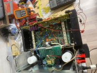
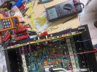
Just to explain few details:
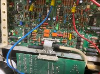
-I have disassembled the faulty channel to be able to work better with. I constructed a short connection between VSMB and CG board (as you see in third photo).
- Don't give importance on the RIFA (10000uf/100V, main power supply) and KEMET (1800uf/200V) capacitors. I just had them in lab and used them to avoid damaging the new (and extremely expensive) CDE DCMCs caps.
The other channel is working correctly, although i have not performed any upgrade there yet.
Th.
Mooly: few photos of what i mean. if you need more or other infos, just let me know.
It is circuit diagrams rather than pictures that are needed
I just looked at the other thread and the service manual and at the risk of having skimmed the details quickly do look pretty straightforward in concept.
You have in essence two complementary 'amplifiers', one for the plus rail and one the negative and with a reference voltage for each. The voltage setting preset simple alters the gain of the 'amplifier' stage to give the desired output.
The reference is fed from the output of each amplifier.
If your is anything like that then it shouldn't be to hard to diagnose but and it is a big but, if your model is different or circuit references are different then it becomes impossible to describe what to check unless you can navigate your own way around what you have and locate the various parts.
For example in that pdf CR206 is the reference source (Zener) and its fed from a constant current source CR204.
That voltage is applied to the input of the 'amplifier'. The gain is set by R225 which is the feedback resistor and the preset.
So things to check on yours are the reference voltage. Compare between each side.
Check the unregulated supply is sufficient.
Check the 'amplifier' stage can actually deliver the current asked of it.
Hi,
i refer to the diagram of the ML 336. It seems that it is the same circuit also in ML 335 (except the 2 additional power transistors per side/per channel - 335 has 6 per side instead of 8).
So according to this schematic the Vreg +,- are adjusted by the R110 and R153 pots (10K, Burns) accordingly.
At this part, i can not see any CR206 or CR204 (in fact not in the whole circuit, unless i'm getting blind from the many hours on schematic.... possible). The highest numbers i can see are the CR203 in optotransistors circuit, which (surprisingly!) have the pins 1 and 2 shorted with soldering. Is this normal?
Where should i check for the CR204/CR206?
So... it seems very similar to the one I described in its concept.
Two mirror image amplifiers, each with its own reference voltage applied to the input via Zeners CR100 and CR102.
Feedback is alterable via the preset in just the same way to set the output voltage.
I can't figure out what the 500 ohm preset is for as it appears to act on Q114 to bring it into conduction but with a 10k to ground in its collector... I'm struggling to see its function at this time
Your incorrect voltage output should be able to be diagnosed though. Check the reference voltages are similar between each side (one will be negative and one positive) and also always check the regulator has enough raw input voltage to work with.
Q110 seems to be some form of current limiting sensor and so the voltage across R136 (is it), the 49.9 ohm should allow you to compare current draws.
From practical point of view high voltages and high value resistors often don't play nicely together and resistors failing high in value is a common scenario generally. So things like those 20k's and anything high value and with a few tens of volts across it could be suspect.
Your incorrect voltage output should be able to be diagnosed though. Check the reference voltages are similar between each side (one will be negative and one positive) and also always check the regulator has enough raw input voltage to work with.
Hi Mooly,
could you be more specific pls? What should i check or change?
In general, i have inspected nearly all components, especially resistors and diodes. From the measure or visual point of view, all look fine.
I would rather suspect an active component (transistor) or a capacitor (like the cheap blue Philips (22uf) than a resistor, but i can not check them without removing the board from heatsink. And i would prefer to avoid it (if possible) for obvious reasons....
Probably the C100/C101, C104/C105, C111/112, C115/116 can cause this problem?
I'm not sure either what the 2x 500 pots are used to (another regulated voltage to VG board perhaps or feedback), but the P57 is the connector to the Voltage Regulator board.
I would begin by checking that both Zeners have the same voltage across them. That diode type comes up as a 60 volt device. You should see similar voltages on the 22uF caps at the input.
Remember to compare one side to the other realising the voltages are negative on one and positive on the other.
Check the raw unregulated supply going into the regulators is high enough. Those are the - and + Pre Reg points.
Your description of the fault is odd in that max voltage occurs in the middle of the range because the gain of the circuit should keep increasing as the preset is turned.
So that needs careful investigation... begin by checking the points mentioned.
Don't discount anything. Has the unit a hidden history? Could that other preset that I can't just figure out have been turned in the past?
A fault like this is just as likely to be a resistor as much as anything else... not guaranteed but trust me... they are a very very common failure point in any high voltage equipment.
If you don't want to isolate them to measure then try and deduce voltages.
The two series 20k's should have equal volt drops across them. The 10k preset and 13k7's are another chain. Get the calculator out and using the meaured voltages end to end on the chain calculate the voltage expected across each.
Feel them (beware voltages). Is one resistor hot and one cool. You have two 'regulators' there and both should be the same.
All the 500 pot does (its the equivalent of a bias preset in an amplifier) is allow the base voltage between the two outputs to increase and allow current to flow in the 10k.
But why? It is appearing as a load across the output, thats all.
Could it be to do with behaviour at start up but it seems a very complex set up if so.
No idea on that at this point
And don't discount the 10k preset either.
(A quick ohms law calculation will show if it is giving the expected voltage as measured across it end to end. For example with 103 volts output you have a total resistance of 13k7 +13k7 +10k which is 37.4k. Total current is 103/37400 which is 2.75 milliamps. Voltage across 10k is 0.00275*10000 which would be 27.5 volts. Same methodology applies to the other resistors)
(A quick ohms law calculation will show if it is giving the expected voltage as measured across it end to end. For example with 103 volts output you have a total resistance of 13k7 +13k7 +10k which is 37.4k. Total current is 103/37400 which is 2.75 milliamps. Voltage across 10k is 0.00275*10000 which would be 27.5 volts. Same methodology applies to the other resistors)
Thx for the hints.
I will work on these points tomorrow (if work allows it) and come back with results.
OK
I would begin by checking that both Zeners have the same voltage across them. That diode type comes up as a 60 volt device. You should see similar voltages on the 22uF caps at the input.
Remember to compare one side to the other realising the voltages are negative on one and positive on the other.
Check the raw unregulated supply going into the regulators is high enough. Those are the - and + Pre Reg points.
Your description of the fault is odd in that max voltage occurs in the middle of the range because the gain of the circuit should keep increasing as the preset is turned.
So that needs careful investigation... begin by checking the points mentioned.
Don't discount anything. Has the unit a hidden history? Could that other preset that I can't just figure out have been turned in the past?
A fault like this is just as likely to be a resistor as much as anything else... not guaranteed but trust me... they are a very very common failure point in any high voltage equipment.
If you don't want to isolate them to measure then try and deduce voltages.
The two series 20k's should have equal volt drops across them. The 10k preset and 13k7's are another chain. Get the calculator out and using the meaured voltages end to end on the chain calculate the voltage expected across each.
Feel them (beware voltages). Is one resistor hot and one cool. You have two 'regulators' there and both should be the same.
All the 500 pot does (its the equivalent of a bias preset in an amplifier) is allow the base voltage between the two outputs to increase and allow current to flow in the 10k.
But why? It is appearing as a load across the output, thats all.
Could it be to do with behaviour at start up but it seems a very complex set up if so.
No idea on that at this point
Hi there,
i found some time to work and check values again (could not sleep actually
)So:
BEFORE TURN ON
R106: 19,98K (nominal 20K)
R107: 20R
R109: 10K (nominal 13,6K)
R110: 14,5K (nominal 10K pot)
R116: 10,4K(nominal 13,6K
CR100: good
R140: 20K (nominal 20K)
R141: 20R
R151: 10,8K (nominal 13,6K)
R153: 8,82K (nominal 10K pot)
R154: 10,82K (nominal 13,6K)
CR102: good
SWITCHED ON
Vunreg: +86,3V / -86,3V
Vpre_reg: +131,6 till +131,8V / -131,9 till -132,0V
Vreg: +115V (can be adjusted normally) / -103,4V (max possible value)
Voltages:
R106: 0,071V
R107: 0V
R109: 42,6V (stable)
R110: 29,98V (stable)
R116: 42,7V (stable)
CR100: 61,8-62,1 V
R140: 0V
R141: 0V
R151: ~37,3V (not stable)
R153: ~28,48V (not stable)
R154: ~37,1V (not stable)
CR102: 61,0-61,2V
In general, similar but not same values....! Still it is not possible to increase the -Vreg over 103-104V.
No significant difference in temperature of resistors (when i 'feel' them). Probably the (+) side is a bit warmer, logical as this part works.
Can you conclude somewhere?
Change everything and see what is going on?
BTW, Mark Levinson refers to the 500R pots and the circuit around them, as REGULATOR BIAS (whatever this means).
Any other idea?
Th.
Hi Theodore,
This is exactly the problem that you get when Vreg+ and Vreg- are not the same .
Look here for an explanation why.
Mark Levinson No.27 amplifier,,,NEED HELP
Hans
Hans,
you said yesterday that the bias problem occurs when +Vreg and -Vreg are not the same within a 0,1V margin.
So today, I tried to reduce the +Vreg (which can be adjusted) to be equal with -Vreg (at about 103,5 V). Nothing changed, obviously cause the -Vreg circuit is not working properly for unknown reason.
Any idea about what this 'unknown reason' might be?
Thx.
Hi Thebet,
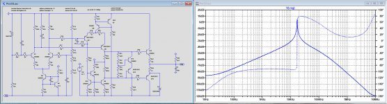
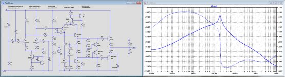
I've put your supply in LTSpice, hoping that you can use this.
In the first image below, I have shown the power supply rejection ratio, assuming that on your Amp board there is still a 330uF connected to Vreg.
Looking at the graph, I'm not really impressed by this PSRR.
When removing C113, it becomes already a lot better, see second image.
Anyhow, you can use the Sim file and compare all the voltages in your Amp.
Hans
Attachments
Hans,
you said yesterday that the bias problem occurs when +Vreg and -Vreg are not the same within a 0,1V margin.
So today, I tried to reduce the +Vreg (which can be adjusted) to be equal with -Vreg (at about 103,5 V). Nothing changed, obviously cause the -Vreg circuit is not working properly for unknown reason.
Any idea about what this 'unknown reason' might be?
Thx.
Do you have a scope ?
In those cases as you mention, there is in most case an oscillation going on, making your DC measurements rather useless.
Hans
- Status
- This old topic is closed. If you want to reopen this topic, contact a moderator using the "Report Post" button.
- Home
- Amplifiers
- Solid State
- Mark Levinson No 335 - NO Bias in one channel / NEED HELP