Thanks for reading me:
After i repaired the speaker protection board of that amplifier, all was ok.
So I then proceeded to adjust iddle current, got it, then DC offset. Oh, bboy.
At that stage, on the left channel, after first seeing normal readings while moving the trimpot to get to the correct setting, suddenly readings were all over the place and did not respond to my turning the trimpot.
I played music to earphones, to find that there was no sound on left channel. Only distorted crackles on peaks.
I took out the board and took out the trim pot, measured it as being ok from end to end and from the moving wiper. Cleaned it anyway and retested as OK.
And, i resoldered 7265 that had broken solder joints. That component was probably the one acting up (relays clicking) when i pushed away the supply wires (touching 7265?) to have access to the trimpot. (BTW why do these (TO126?) stand so high on their legs, wrapped in shrink tubing??) I also reflowed the connector for the supply lines, just to be sure.
I reinstalled the board. The audio is now heard on left channel. Distortion is hard to qualify on cheap earphones and with my old ears and in haste not to blow anything up.
But: i can't adjust either Iddle Current (.2mv) or DC Offset (160mv). Trim pots have no effect. With power off i rechecked that DC offset trimpot and it was still behaving correctly.
I probed the supply lines as deep as i could, including around some transistors (results i should not quote now, but maybe of interest: 7261 is E 53.2V, B -52.7V, E -53V). All seemed normal in my limited understanding of those circuits. I tested in circuit the first components branching out of + and -VB, and double diode tested 7265. I did not probe under the copper shield (housing 7251, 7253, 7255, 7257, 7259) yet.
I hope there is an obvious "classic case" component causing that anomaly, which some knowledgable and experienced person here will point out to me.
I saw that i can easily unsolder that copper shield and probe those components. If someone points me to what i should measure there?
BTW all i have is a digital multimeter. It can test semiconductors. It also has capacitance capability but seems unable to measure >20?uf . To find good units in my NOS stash i rely on reading DC volts, discharge, remeasure DC volts, do long Ohms test, and remeasure DC volts to see if it went up. Served me well to date ;-)
So with that multimeter, can i test transistors IN circuit with the double diode test? i'm afraid to kill them with heat from the iron, but will manage a heat sink (like, my wife will hold the longnose pliers ;-)) if necessary.
Thank you all for your insights and help.
service manual:
https://www.hifiengine.com/hfe_downloads/index.php?marantz/marantz_pm7200_service.pdf /url
Last edited:
I would test the driver transistors and associated components too.
Hmm. ok. Where are those?
 Under that copper shield, or are these the first ones on the power amp (after the "split")?
What tests should i do? Do i simply follow the supply/bias lines?
Can i test transistors and diodes in circuit?
Sorry for my noobiness


You can do a diode check on driver transistors.
BC is high resistance one way and low resistance the other
Same for BE.
CE should be high resistance both ways.
Ok will do. That double diode test i know about, at least!
Is this the output stage you are working on:
View attachment 879826
?
And is one channel (the right channel) working OK?
Yes, it's that output stage exactly.
I have sound on both channels, but can't adjust Idlle nor DC on left channel.
For what it's worth, i already probed 7273 and 7271 (drivers, i gather?)
7273: C 55.8V, B 1.5V, E 0.99V
7271: C -55.8, B -1.6, E -1.048V
between 6271 and 6279 is 1.32V,
between 6269 and 6267 is -0.33V,
between 6267 and 6265 is -1.6V
I am in the process of removing the copper shield, man lots of heat dissipation there. I need a solder sucker, braid is not quite good enough. Will try with the butane big tipped iron...
You probably need to measure some more for a start:
C-voltages on:
7251/7253
7257/7259
7263/7265
- in both channels.
In you shoes I would also solder out 7267 and check if it is OK.
A cheap LCR-meter could be handy - something like these:
https://www.ebay.com/sch/i.html?_from=R40&_nkw=lcr+meter&_sacat=0&_sop=15
C-voltages on:
7251/7253
7257/7259
7263/7265
- in both channels.
In you shoes I would also solder out 7267 and check if it is OK.
A cheap LCR-meter could be handy - something like these:
https://www.ebay.com/sch/i.html?_from=R40&_nkw=lcr+meter&_sacat=0&_sop=15
Last edited:
You probably need to measure some more for a start:
C-voltages on:
7251/7253
7257/7259
7263/7265
- in both channels.
2 of them already probed on left channel:
7263 C -1.67V
7265 C 1.6V
In you shoes I would also solder out 7267 and check if it is OK.
A cheap LCR-meter could be handy - something like these:
https://www.ebay.com/sch/i.html?_from=R40&_nkw=lcr+meter&_sacat=0&_sop=15
Exactly the meter i was aiming for! will order this. And a solder sucker. And probe clips. and...
I'll get to these other trans once the copper shield is off. Then that big 7267.
Thanx!
I'll get to these other trans once the copper shield is off. Then that big 7267.
Better to disappoint you now than step by step later on - in a case like this it is frequently a better start to unsolder all transistors in bulk and check all of them out of circuit. While they are out you can also check more resistors (yes, sometimes they also turn faulty) and diodes in the circuit.
")
An average small transistor should tolerate well (at least) 2 seconds of solder pad heating via solder wick, bigger transistors tolerate more - I have not heard anybody recently "heatsinking" the transistor legs in a routine "simple" repair situation.
In you shoes I would also solder out 7267 and check if it is OK.
Tested 7267 out of circuit.
With red probe on Base, Diode test gave: .649V to Collector and .651V to Emiter, nothing between C and E. And nothing with probe reversed.
Resistance is 19.4MOhm B to C, 19.9MOhm B to E. Infinite E to C and with probes reversed.
It was recognised as nPn Ecb on the multimeter's Transistor test, 134 Hfe. Same if reversed in the socket (with bcE pinout of course).
I guess this transistor is good? Correct?
I am still fighting to get that heat robber copper shield off (i fudged up a solder sucker with the ShopVac
, praying for no static troubles) I guess i'm at the stage of heating and pushing the lugs through, when i find how to support the board against bending.So i'll be able to probe in there soon.
After i check the supply network around 7263.
thank you!
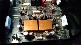
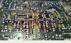
I am still fighting to get that heat robber copper shield off...
You could post some photos of the amp internals - we could sympathize with your efforts easier
You could post some photos of the amp internals - we could sympathize with your efforts easier
Sympathise away!
Attachments
80W soldering iron would do it ...
oups!
45 Watts, here. But wait! i think somewhere i have a soldering tip for the BernZomatic plumbing torch...

I ordered a mega328 ESR meter, and a solder sucker. 1 week?
I tested a lot of diodes and fusible resistors, those i thought could be tested in circuit. All tested ok.
A lot more tests to do, especially after i remove the copper shields. I at least succeeded in tinning the old butane irons, those could help. Never found a tip for the BernZomatic plumbing torch (would ha been quite adequate).
So i plan in a few days to annotate a .pdf with my readings and post it, hoping someone more experienced than i will be there to read it and advise.
Unless i find the guilty party...
Just be careful and not overheat the board.
igottheshieldsoff igottheshieldsoff igottheshieldsoff igottheshieldsoff
! ;0 GOT
THE ;O SHIELDS ;D OFF ;"!!!!!!! :banana::jump::banana:
Attachments

igottheshieldsoff igottheshieldsoff igottheshieldsoff igottheshieldsoff
! ;0 GOT
I got the meter and solder pump today.
I calibrated the meter, rigged pins and alligators to extend the ZIF socket, tested a few cans in my NOS and 7267 of the Marantz that i had taken out (it's good :-().
That puny meter looks useful.
For Google customers searching, a pretty good manual (not supplied with the lower priced item from Amazon.ca) for "LCR-T4 Mega328 Component Tester" is here:
Page not found – kookye.com...
Now brace yourselves, friends. Data storm coming soon. Thanks for weathering it.
(i should not play with those words, sorry for those who live through those very real weather storms down south)
Attachments
- Status
- This old topic is closed. If you want to reopen this topic, contact a moderator using the "Report Post" button.
- Home
- Amplifiers
- Solid State
- Marantz PM7200 Can't adjust Idle Current or DC Offset