...What do you think about this? Of course, some "internal" delay is needed I suppose...
Your explanation is not quite correct for the Yamaha circuit.
That circuit uses some hysteresis in the loop and works fine even with no delay.
The problem is that the hysteresis is not very well defined, seems to depend on the Early effect in the MOSFET driver, if I understand it correctly.
If we eliminate the hysteresis then the self oscillation is determined by the phase shift (and delay) around the loop, like the Putzeys' circuit.
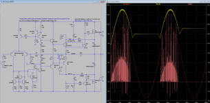
I tried to do a demonstration circuit that uses the well defined hysteresis of the Spice controlled switch, the SW component.
This should show the hysteresis effect very clearly but there is some sort of calculation problem with LTSpice - many anomalous current spikes.
I have seen this before but never worked out the exact cause or the correct fix, maybe needs some parameter set.
The correct behaviour is visible as the sine shaped outline.
You know how to fix this?
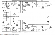
In the mean time I will try to do an actual circuit.
Best wishes
David
Attachments
Last edited:
Can you explain a bit more? How Early effect causes hysteresis in a circuit?The problem is that the hysteresis is not very well defined, seems to depend on the Early effect in the MOSFET driver
Can you post a ASC file?This should show the hysteresis effect very clearly but there is some sort of calculation problem with LTSpice - many anomalous current spikes.
I have seen this before but never worked out the exact cause or the correct fix, maybe needs some parameter set.
The correct behavior is visible as the sine shaped outline.
You know how to fix this?
Can you explain a bit more? How Early effect causes hysteresis in a circuit?
I was mistaken. I will have to study this more.
Can you post a ASC file?
Sure. The current spikes are from the Schottky diode.
Attachments
Sure. The current spikes are from the Schottky diode.
Maybe I should say "thru" the Schottky diode.
Drawn from the capacitance of the FET by the instantaneous closure of the switch I suspect.
I am out of practice with LTSpice but it starts to come back.
Best wishes
David
Last edited:
I'm not sure why you are looking for hysteresis. All you need is gain and enough phase shift and you have an oscillator. OK, it also has to be DC stable. Hysteresis is used with simple RC oscillators but we have an LC network in the feedback loop which is going to provide ~180 degrees of phase shift at some frequency, plus a small added delay from the 20nF caps, which, BTW, may not be that small depending on the impedance where it is used and frequency. This is the same as a UCD amp where the output filter is most of the frequency determining part of the feedback loop. A non-synchronous switch has no dead band but the main reason self oscillating UCD amps sound good is that the output operates in class AB so there is ~no dead band.
I'm not sure why you...look...for hysteresis. All you need is gain and...phase shift and you have an oscillator.
The Yamaha patent on which this amp appears to based is explicitly a hysteresis based circuit.
It's worth a look at the patent link that "Jony" posted.
It's true that gain and phase shift will produce an oscillator but Bruno Putzeys pointed out that this simple linearised analysis is not really correct for a circuit like this that is very non linear.
He did a more detailed analysis that apparently includes both phase shift and hysteresis/non linearity.
He discusses the relation between the two approaches but I don't completely understand this yet.
So I decided to start with hysteresis circuits because they were what people tried first, Bruno came later.
... UCD amps...output operates in class AB so there is ~no dead band.
I don't understand what you mean by this.
The UCD amps are Class D and the transistors hard switch.
Best wishes
David
OK, I did more sims and came to the conclusion that a hysteresis circuit is sub-optimal for a wide band amp.
Not really a surprise, Bruno Putzeys is no fool.
For a sub woofer application like this it works fine, but it looks possible to improve the efficiency and lower the distortion with a power supply based on UcD circuitry rather than Yamaha.
So probably no point to continue in this thread.
Thanks to the OP for the initial circuit schematic and the start of the discussion.
David
OK, I did more sims and came to the conclusion that a hysteresis circuit is sub-optimal for a wide band amp.
Not really a surprise, Bruno Putzeys is no fool.
For a sub woofer application like this it works fine, but it looks possible to improve the efficiency and lower the distortion with a power supply based on UcD circuitry rather than Yamaha.
So probably no point to continue in this thread.
Thanks to the OP for the initial circuit schematic and the start of the discussion.
David
Just by accident I found this article on the web
(PDF) A Class B Switch-Mode Assisted Linear Amplifier
Attachments
Just by accident I found this article on the web...
Useful find.
I think I had a quick look at this previously but wasn't very interested at the time because I want a serial architecture.
That way I can use the switch Mosfets as protection for the output transistors from short circuits and also protect the speakers from output transistor failures.
All with no extra components or speaker protection relays.
But I should have looked more closely because the circuit is useful to show their implementation of low-side Mosfet drivers and comparators.
So thanks.
Best wishes
David
- Status
- This old topic is closed. If you want to reopen this topic, contact a moderator using the "Report Post" button.
- Home
- Amplifiers
- Solid State
- I need help understanding schematic of Yamaha subwoofer