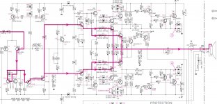
It looks likethe total rail voltage is +/- 180 volts, but the MOSFETs are only rated at 200V. So the inner ones (Q28,Q34) are doing the almplification. The outer ones (Q41, Q43)are reducing the supply voltage across the others so they stay within there voltage ratings. They do this by tracking nominally 4.2V voltage above the output.
Note that as the output swings below -5V the inner ones (Q29,Q34) are supplied via the Diodes D37, D38, so the Drain is clamped to Gnd, this also stops the voltage across Q41,Q43 exceeding there 200V limit.
Note that as the output swings below -5V the inner ones (Q29,Q34) are supplied via the Diodes D37, D38, so the Drain is clamped to Gnd, this also stops the voltage across Q41,Q43 exceeding there 200V limit.
It's a tracking buck regulator similar to this P-S Series - EEEngine - Power Amplifiers - Professional Audio - Products - Yamaha - Other European Countries
strange with C48,C49
Maybe something to do with the A.N.I.C and the motion control of woofer
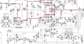
I could be mistaken but C48/C49 look to me like a pair of bootstrap caps to keep maintain constant voltage between the R108/R112 and R109/R113 junctions and between those junctions and the output. This maintains the proper operating points for Q24 and Q25, which then control and maintain the proper operating point for the output stage cascode transistors (Q28, Q33), which then maintain a constant and low VDS across the output FETs.
Switching class H
Yes. It's important to realize that the upper FETs Oscillate/ switch. These PWM regulators maintain ~4Volts across the lower linear mode MOSFETS, so we have a hybrid class-D and AB amplifier.
It's a tracking buck regulator similar to this P-S Series - EEEngine - Power Amplifiers - Professional Audio - Products - Yamaha - Other European Countries
Yes. It's important to realize that the upper FETs Oscillate/ switch. These PWM regulators maintain ~4Volts across the lower linear mode MOSFETS, so we have a hybrid class-D and AB amplifier.
Yes. It's important to realize that the upper FETs Oscillate/ switch....
I have read about the Yamaha switcher/hybrid but this is the first time I have looked at a circuit.
I am not surprised the OP was confused, it's not obvious, to me anyway, how the oscillation is driven.
Do you have any more explanation/information?
Looks like an innovative and clever implementation, a pity there is so little interest.
Best wishes
David
The switching sections are self oscillating like a UCD, but operate in "non-synchronous" mode in PWM regulator terms, ie the diodes provide current to the inductors when the FETs are off. So, actually the voltage on the linear mode FETs does increase when the audio swings the other way and they are off.
...but operate in "non-synchronous" mode...
Thanks, not sure I understand exactly what you mean by this but I stared at the circuit (for quite a while) and eventually worked it out.
Pretty clever - simple but effective.
It seems the oscillation frequency would be determined by the rise and fall times of the transistors, parasitics and other somewhat ill-defined characteristics.
The drop across TP1-TP2 is involved and has to be adjusted to within 30 mV to 150 mV - but I can't see how this is done, where's the trimmer?
Have you any experience with reliability and serviceability of these or similar amps?
Best wishes
David
Last edited:
...It seems the oscillation frequency would be determined by the rise and fall times of the transistors, parasitics and other somewhat ill-defined characteristics...
OK, a closer look shows oscillation frequency mostly set by the resonance of the inductors with capacitors C59-61.
Still need a little extra phase shift to make it 180 phase reversal, so the second order parasitics and such are involved but not too much.
Still can't find the damned trimmer.
David
Last edited:
The oscillating frequency is pulled down by C57, C58.
If there is a trimmer, it's R236, R237.
A "synchronous" buck converter uses a transistor on the lower side of the totem pole that switches out of phase with the upper transistor, vs a non-synchronous buck converter that just allows the inductor to pull current from diodes to ~ground when the (upper) switch is off.
Buck converter - Wikipedia
Here you have a US patent on this circuit:
US5347230A - Amplification circuit
- Google Patents
And a LTspice simulation file
US5347230A - Amplification circuit
- Google Patents
And a LTspice simulation file
Attachments
Strange circuit but i guess that its more suited to class d forum, the reviews has struck hard for not reaching low enough nut i have been listening to music for a few days and its pretty goood.
There are 2 different patents in this circuit, one is the old carlsson/acepro/yst negative impedans speaker approach and the other is as already mentioned in thread.
I now understand the schematic/design and i feel educated.
Thanks everybody!
There are 2 different patents in this circuit, one is the old carlsson/acepro/yst negative impedans speaker approach and the other is as already mentioned in thread.
I now understand the schematic/design and i feel educated.
Thanks everybody!
...frequency is pulled down by C57, C58.
C57/58 are only 0.022 uF and shunted by the diodes so I expected them to be unimportant compared to the 4.7 uF caps that resonate with the inductors.
But I could be mistaken, will have a closer look.
If there is a trimmer, it's R236, R237.
That's what I expected too, but they are shown on the schematic as fixed, shown on the PCB illustration as simple resistors and in the parts list also.
The manual says to adjust "VR1" but it doesn't seem to exist- typo or bad cut-and-paste from a earlier version maybe?
A "synchronous" buck converter uses a transistor on the lower side of the totem pole that switches out of phase with the upper transistor, vs a non-synchronous buck converter that just allows the inductor to pull current from diodes...
OK, I know this use, I just wondered if you meant it differently.
I did not at first realise that the oscillation was not switched on while the amplifier was close to quiescent, has a small dead band.
So I wasn't sure if you meant this, but I see now that you were clear, I just didn't read it carefully.
Here you have a US patent on this circuit:...
And a LTspice simulation file
Thank you.
... its more suited to class d forum
...the reviews has struck hard...
Definitely not Class D, so it's perfectly appropriate here.
It looks fairly well conceived so I wouldn't worry about the reviews if it performs as well as it should.
I am also educated, had planned to study this anyway.
So thanks to you too.
Best wishes
David
Last edited:
...And a LTspice simulation file
Hi Jony
I finally had the time to run this and experiment a little, the behaviour is not quite what I expected.
Is it your own circuit? I would be keen to talk about and analyse it more deeply if you are familiar with it.
Or with any one else who's interested, for that matter.
It's an excellent start so thanks once more.
Best wishes
David
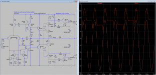
No, I just add the "Yamaha circuit" into the existing (random) amplifier schematics I have found in LTspice.Dave Zan said:Is it your own circuit?
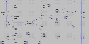
I've added Q15, Q16, Q17, M1, and D7. And I lowered the output stage quiescent current so that Q17 is OFF at the idle.
And we can simplify the circuit
I'm interested to see your analyze this interesting circuit, and others are probably also.Dave Zan said:I would be keen to talk about and analyse it more deeply if you are familiar with it.
Attachments
Last edited:
I just add the "Yamaha circuit"...And we can simplify
...
I'm interested...and others are probably also.
Thank you for the simplified version, best to start from basics.
And thanks also for your interest, but I am not sure many others are, I have tried to start a discussion of efficient switch mode Class H but had few responses.
So it's nice to have a chance to discuss this, I like to see other people's idea's and when I try to explain my own I find it helps me too.
So, here's the first observations-
The two circuits seem to have poorly defined hysteresis, I commented about the Yamaha YST 1500 circuit that the frequency looked poorly defined then back tracked a bit because I expected the inductor/capacitor resonance would constrain it fairly well.
But I now think I didn't properly understand the inductor/capacitor interaction.
This issue of phase shift from the inductor/capacitor filter and it's relation to hysteresis is not simple.
Bruno Putzeys mentions it in the Ncore whitepapers but mainly to say that no one else has it worked out as well as he has.
So I need to reread the Class D literature to see what is applicable here, because the circuits are essentially similar.
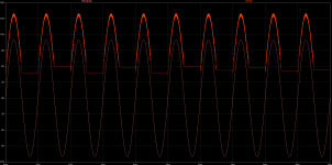
Here's a plot of the outputs of your simplified circuit.
At 1 kHz it's noticeable the way the Rail potential baseline jumps around.
Class-D can have some kind of similar problems IIRC.
At 7 kHz the rail does not track well at all.
(I know the OP was about a subwoofer amp but I want a full audio frequency power amp)
By 20 kHz it's completely unusable.
Best wishes
David
I assume the 220 uH value of the -ve side inductor was to help it solve the initial conditions.
(Curious that if the values of both side are identical then LTspice has trouble.)
I altered the inductor on the -ve side from 220 uH to 150 uH to make it more similar to the +ve one.
Attachments
Last edited:
Yes for sure.The two circuits seem to have poorly defined hysteresis
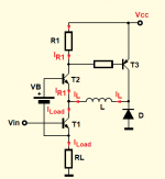
But if for simplicity we will treat the inductor as a current source.
We can see the at the beginning when I_L = 0A all the load current is flowing from Vcc through R1 and T2 thus, we turn on the T3 and the inductor current will start to flow and rise at a rate equal to VL/L = A/s (ampere per second).
But as the inductor current increases the R1 resistor should decrease with a similar rate because I_load = I_R1 + I_L.
If this is the case, at some value of a load current the R1 current will be too low to sustain a voltage drop needed for T3 to stay open.
If T3 tuns-OFF the inductor will start a "discharge" phase. And the inductor current will start decreases process at the rate of (V_Out + VB )/L.
Decreasing I_L current will increase the I_R1 current. And if this current is high enough the T3 will open once more and the cycle will repeat itself.
What do you think about this? Of course, some "internal" delay is needed I suppose as in every self-oscillating D class amplifier.
Also, the frequency of oscillations of a self-oscillating D class amplifier is also not well defined but we have to live with it.
Dave Zan said:I assume the 220 uH value of the -ve side inductor was to help it solve the initial conditions.
(Curious that if the values of both side are identical then LTspice has trouble.)
I altered the inductor on the -ve side from 220 uH to 150 uH to make it more similar to the +ve one.
No, I just want to see how the large inductance value will decrease the switching frequency.
Attachments
Last edited:
- Status
- This old topic is closed. If you want to reopen this topic, contact a moderator using the "Report Post" button.
- Home
- Amplifiers
- Solid State
- I need help understanding schematic of Yamaha subwoofer