....My guess is that the output transformer phase was wired wrong....
That would tend to oscillate in the *middle* of the audio band.
There's an infinite number of ways an amp can squeal supersonics.
I would argue it's not the inductor that guards the amp from capacitive load but the R we put in parallel. The role of the inductor is to bypass the R at low frequencies and avoid power losses on the serial resistor plus keep the dumping factor low.
For example, putting a 2-4 ohm resistor in series to output would make every amp completely immune to capacitive load. With obvious side effects.
For example, putting a 2-4 ohm resistor in series to output would make every amp completely immune to capacitive load. With obvious side effects.

Use common emitter or common source (a la Pass F5) output stage and the problem with capacitive loading vanishes...
Expanding Bonsai's reply - The output stage cannot be separated from the rest of the topology for a stability result. If just one element could give control, then amp design would be easy.
Expanding Bonsai's reply - The output stage cannot be separated from the rest of the topology for a stability result. If just one element could give control, then amp design would be easy.
I only partly agree. If you have designed the amplifier with a proper phase/amplitude margin, the stability of the amplifier is not worsened by capacitive loading with a common emitter/source output stage, in opposite to a common collector/drain output stage.
Exactly Spadski -- that's why you have compensation capacitors ( in most designs ) that all parts will work in harmony at low distortion of any sort /stability /active parts taken into account in relation to all parts of the circuit and so on.
People buy books by D.Self/JLH to help with their own designs do they not realize months of thought on designs went into them?
When you read the whole design philosophy that goes into them each section having to be smoothly connected to the next you will see its no "5 minute job " .
Tear down an audio IC or a power amp IC and read up on the long lines of maths that have gone into them to make them stable and work together .
I think shops like Radio Shack etc have made people think -- I will go and buy an input section (block ) -- a VAS section -a driver section and with my basket as I pick them off the shelves an output section , now which one will I choose - BJT/Mosfet /Vacuum Tube -- gee ! I like that red colored block it will go well with my wallpaper.
The stability margin is always affected by a capacitive load if you do not provide some way of isolating the amplifier from the capacitive Load. Very easy to see this in a sim as I explained in my earlier post.
You can of course comp the amp so that it tolerates capacitive loads without the inductor, or, so that it instead relies on A bit of the cable inductance to do the job. But, if you do this, you are giving away loop gain which is a valuable tool for reducing distortion in my view.
You can of course comp the amp so that it tolerates capacitive loads without the inductor, or, so that it instead relies on A bit of the cable inductance to do the job. But, if you do this, you are giving away loop gain which is a valuable tool for reducing distortion in my view.
Last edited:
The stability margin is always affected by a capacitive load if you do not provide some way of isolating the amplifier from the capacitive Load. Very easy to see this in a sim as I explained in my earlier post.
You can of course comp the amp so that it tolerates capacitive loads without the inductor, or, so that it instead relies on A bit of the cable inductance to do the job. But, if you do this, you are giving away loop gain which is a valuable tool for reducing distortion in my view.
I still don't agree. My point is: With a higher capacitive loading, the loop gain drops, so the phase margin is not worsened.
This can be seen clearly if you apply a square wave to the input of the amplifier and look at the amplifier response.
The cure in almost all cases is to place a small inductor in series with the amplifier output (‘output coupling inductor’). Using modern high fT devices, anything more than 0.6 uH almost always does the trick.
Output Coupling Inductors
I've seen a few amps that just do 1 or 2 turns on a small ferrite core between the output of the power amp module and the speaker jacks. To me that seems like it opens a can of worms with the linearity of ferromagnetic materials, but perhaps I'm mistaken.
Out of curiosity, you mention that with output devices with a high transition frequency that a relatively small output inductor is enough. Can anyone explain why that is?
Please see the link I posted a few pages back.
Its never a good idea to use ferrites for the output inductor because the currents are very high and you run the risk of saturation and that can lead to instability issues (the inductance falls to zero when the ferrite saturates) and non-linearity.
A 0.6-0.8 uH air-core inductor is c. 10 turns on a 1cm former and you shunt that with a 2.2 Ohm resistor and it does the job for most modern amps assuming they are correctly compensated in the first place.
Last edited:
I still don't agree. My point is: With a higher capacitive loading, the loop gain drops, so the phase margin is not worsened.
This can be seen clearly if you apply a square wave to the input of the amplifier and look at the amplifier response.
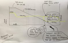
The loop gain drops at HF and the phase margin degrades without the output L(R) network. Again, please see the link to the presentation I posted a few pages back that makes this mechanism clear. This is straight control theory stuff - you can see the upper pole migrate down in frequency and up in magnitude as you increase the capacitive load. As soon as the pole is above 0 dB you have a problem because the roll off slope is now intercepting the 0 dB gain line at 40 dB/decade. The output L(R) network solves that problem.
I still don't agree. My point is: With a higher capacitive loading, the loop gain drops, so the phase margin is not worsened.
This can be seen clearly if you apply a square wave to the input of the amplifier and look at the amplifier response.
Are we talking about the same design? The OP mentions oscillations in his sim. As there is no LTspice version I cannot confirm.
Common emitter output stage
I'll try to explain why I think it is better with a common emitter output stage.
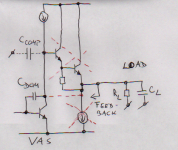
Referring to the schematic with a darlington output following the VAS, we are ensuring the stability by selecting a proper value of C_Dom. The Miller-effect make it possible to use a relative small value of this capacitor. We could, however, use a capacitor C_Comp instead (or in addition). However, then the capacitor had to be much larger (Slew rate becomes a problem).
Now, what happens if we remove the Darlington output stage and use the VAS as the output stage instead. The capacitive loading C_L now is at the collector at the VAS. (We have now removed the possibility that the darlington is oscillating because of the loading capacitor C_L.)
So if you mean that a commom emitter stage is not better than a emitter follower output stage, then you have to explain to me why a larger C_Dom causes more instability.
I'll try to explain why I think it is better with a common emitter output stage.
Referring to the schematic with a darlington output following the VAS, we are ensuring the stability by selecting a proper value of C_Dom. The Miller-effect make it possible to use a relative small value of this capacitor. We could, however, use a capacitor C_Comp instead (or in addition). However, then the capacitor had to be much larger (Slew rate becomes a problem).
Now, what happens if we remove the Darlington output stage and use the VAS as the output stage instead. The capacitive loading C_L now is at the collector at the VAS. (We have now removed the possibility that the darlington is oscillating because of the loading capacitor C_L.)
So if you mean that a commom emitter stage is not better than a emitter follower output stage, then you have to explain to me why a larger C_Dom causes more instability.
Attachments
The overall topology is the embodiment of the design objective. Separating elements without reference to the design objective is meaningless.
You have missed my point: If you load the VAS collector with a higher capacitor, the open loop breakpoint is reduced. Your figure assumes no change in the open loop bandwidth.
You can do that with a resistor. And either way it’s entirely suboptimal.
In any amp, you have to ensure the loop gain intercepts the unity loop gain frequency at 20dB/ decade to ensure unconditional stability. The problem with C loads is they move the upper pole around so you cannot guarantee the unconditional stability requirement unless you really hobble the loop gain by doing what you suggest.
In any amp, you have to ensure the loop gain intercepts the unity loop gain frequency at 20dB/ decade to ensure unconditional stability. The problem with C loads is they move the upper pole around so you cannot guarantee the unconditional stability requirement unless you really hobble the loop gain by doing what you suggest.
nice notes, but they refer only to opamps not power amplifiers
- Home
- Amplifiers
- Solid State
- Stability of an amplifier under capacitive loading