Cool project!
Out of curiosity:
Why did you choose the Cathodyne phase splitter? I personally like the long-tailed pair, because it provides the same output impedance for both outputs. It also makes it easy to use a balanced input.
Why don't you use a bipolar power supply for the output stage? It's not that much more complex, and you could get around the output coupling cap.
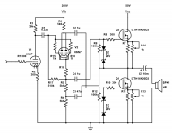
Never bothered with LTP since I usually make a Cathodyne that drives a driver tube (so hardly loaded). It's also simple. Same for the output stage.
The transformer I have isn't centre tapped so that's what I get to play with. It was scrap pulled from a piece of pool equipment.
I also don't really know what I'm doing with SS stuff yet, and I've always thought a directly coupled speaker required servos and protections to avoid DC on the output. The cap coupling negates all of that (except for the thump which a time delay relay will sort out), right?
🙂
Looks like you can get about 30W into 5 ohms at 1% mainly 2nd harmonic distortion for a 0.65Vrms input. You could use a CCS on the input for lower distortion.
I think this means the 6N3P has more than enough gain and I can use 6N6P instead... 0.65Vrms is quite sensitive to me.
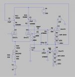
Another idea would be using 6SN7 for all tubes but I don't know if it can drive the MOSFETs, but I think if I parallel both halves of the tube, I could drop it into this circuit in place of the one half of 6N6P. I will draw a modified schematic and post it in a moment.
Edit: Posted it. Also ditched the DC coupling in the input because as the tubes wear it's more forgiving. I haven't calculated R18 yet, but I figure around 220 maybe?
Attachments
Last edited:
The 6SN7 configuration is now almost a LTP ... just move the lower output up and ... add a few resistors ... and remove some parts ... and ditch the input tube!
The 6SN7 LTP would provide a gain of 10 (per leg). With a sufficiently "loud" source, that might be enough to drive the output stage.
The 6SN7 LTP would provide a gain of 10 (per leg). With a sufficiently "loud" source, that might be enough to drive the output stage.
Last edited:
I think it would be difficult to establish stabile output DC voltage (25V) with this setup. You can easily put the output stage on breadboard and test DC behavior first.
I would suggest slightly different arrangement: R8 remains connected to R9 with one end, the other end goes to a 25V reference point. The later can be created with a voltage divider with two resistors and a 220uF capacitor to ground.
I would suggest slightly different arrangement: R8 remains connected to R9 with one end, the other end goes to a 25V reference point. The later can be created with a voltage divider with two resistors and a 220uF capacitor to ground.
The 6SN7 configuration is now almost a LTP ... just move the lower output up and ... add a few resistors ... and remove some parts ... and ditch the input tube!
The 6SN7 LTP would provide a gain of 10 (per leg). With a sufficiently "loud" source, that might be enough to drive the output stage.
I think LTP is not suitable to drive this output stage. Upper and lower FET should be driven differently. Upper is source follower, the lower is common source.
I think it would be difficult to establish stabile output DC voltage (25V) with this setup.
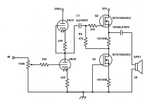
This^^. I tried with slightly mismatched output transistors in Spice and the centre voltage approached the rail voltage. Below is one possible solution, VR1 sets the centre voltage and VR2 adjusts the output stage bias.
Attachments

I think LTP is not suitable to drive this output stage. Upper and lower FET should be driven differently. Upper is source follower, the lower is common source.
You can bootstrap one leg of the LTP to get the appropriate drive mismatch, below is an example of this, a headphone amp I made.
Attachments
You can bootstrap one leg of the LTP to get the appropriate drive mismatch, below is an example of this, a headphone amp I made.
Bootstrapping is good trick, but works well with pentode like devices, that is horizontal lines in Ia vs Ua (Ic vs Uce, Id vs Uds) charts. With triodes is bit complicated.
Yes, it worked well enough in my application (triode OTL driving low impedance headphones) but balance is imperfect for higher impedance loads.
Am I to assume that the mismatch in the PP version will still be a problem in this single ended one?
Yes I guess so. The remedy is to re-connect R6 from the drain of the lower FET to a DC reference somewhere in the middle.
There is usually a wide variation in threshold ("turn on") voltage for mosfets, both between different samples and as the junction temperature changes, so the current you get with simple "cathode biasing" might be quite different to what you were expecting. Just another thing to watch out for. Perhaps like you, I have been mostly building tube designs until recently, and when I built a hybrid design with mosfet outputs I went through a few of them until I got the biasing right (both start-up and steady state).
The tube 6n6p lacks proper bias to operate correctly. It should be more negative than the cathode voltage.
please read and understand post #2....had you read it you will not be making your statement...
Last edited:
There is usually a wide variation in threshold ("turn on") voltage for mosfets, both between different samples and as the junction temperature changes, so the current you get with simple "cathode biasing" might be quite different to what you were expecting. Just another thing to watch out for. Perhaps like you, I have been mostly building tube designs until recently, and when I built a hybrid design with mosfet outputs I went through a few of them until I got the biasing right (both start-up and steady state).
i concur based on simmilar experience...a bit more work, but it was worth it..
Last edited:
btw, i purchased 16n20d2 fro UT Source out of HongKong, i got enhancement mosfets instead....so be carefull...and the funny thing was, somebody sent me a message warning me but i did not listen, mea ultima culpa...
Last edited:
The mosfet models are very basic ones I did myself based on the datasheet. Accuracy is OK at the sort of currents you would see in a audio amplifier but was out at high currents. That said, the GS voltage was -2.14 volts for a DS current of 2.04 amps.
And I just said that there is a lot of variation , hence the need for bias adjustment capability.
And I just said that there is a lot of variation , hence the need for bias adjustment capability.
Last edited:
To test the effect of mismatch I created another model that resulted in -2.055V GS for 2.46A. Models used were:
.MODEL IXTH16N20D2 VDMOS(KP=5 RS=1m RD=0.6 VTO=-3 RDS=20E6 Lambda=0.005 subthres=5m CJO=4.9n M=1.5 a=1 CGDMAX=900p CGDMIN=80p CGS=6200p a=1 VJ=2.6 RG=10m IS=1.37u N=2)
.MODEL IXTH16N20D2B VDMOS(KP=5 RS=1m RD=0.6 VTO=-3.5 RDS=20E6 Lambda=0.005 subthres=5m CJO=4.9n M=1.5 a=1 CGDMAX=900p CGDMIN=80p CGS=6200p a=1 VJ=2.6 RG=10m IS=1.37u N=2)
- Home
- Amplifiers
- Solid State
- Any help? First attempt at a "hybrid" using depletion MOSFETS