Hi Hayk,
I can now see your point about the need for a high VAS/driver current of 300mA! The distortion as a follower without a high VAS/driver current is no better than the previous ones with 20dB voltage gain, for this follower I get 0.03% with 19Vpk at 20kHz and 0.002% at 1W 20kHz. If you are right then a VAS/driver current of 300mA will lower the distortion somewhat. Maybe by a factor of 10?
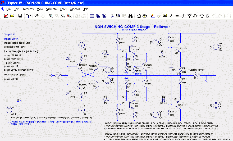
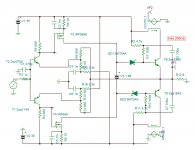
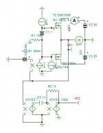
With this follower (and most followers) care is needed with compensation. The Miller caps damp sticking overload recovery and the RC to common stop ringing above 1MHz. Input diodes are needed to prevent latch-up if the input voltage goes above the rail voltage by more than 5V.
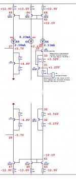
Now with a bootstrapped supply the VAS/driver dissipation is much lower but should be supplied by a separate secondary to avoid dissipating as much power in the dropper regulator to +/-5V as is dissipated by the power transistors. Also Q9 and Q10 cascode transistors need a bias voltage about 2V less than the 5V supplies to keep the collector voltage about 1V above the base voltage. I use 1.7V bias which could be from LEDs fed by 2k2 resistors from +/-5V.
BTW I have been evaluating some 2W SMPS DIP modules by Traco for this purpose. I have tested a 24V to +/-15V 2W module for HF hash. I found it's output can be cleaned up satisfactorily for an audio power amp with a small amount of additional RC output filtering, and the input can be isolated from the main rail with a series pass transistor to allow 25V-55V input. The fixed input 2W version costs only AU$4. The Traco 1W wide input voltage range version costs 5 times as much as a fixed input 2W, that's why I use a discrete external pre-regulator.
I have converted to a follower with bootstrapped V supplies. Driver/VAS is 30mA. Files attached.Goodmorning Ian. Your driver has a load of 800 ohms. To fix the dominant pole at 20khz , you must ground the collectors with 10nf. The maximum slew rate is Imax/10nf. You will need 2× 0.3ma to get 60V/us. This Why the drivers should be mid power transistors of min 40w to dissipate a continues 10w. I suggest you IRF640/IRFP640. At 300ma biased , it gives 93db*+6db VAS gain with Dtot of 0.0077% (mostly to be subtracted by the other pole ) at 20khz 18v p. ...
Hayk
I can now see your point about the need for a high VAS/driver current of 300mA! The distortion as a follower without a high VAS/driver current is no better than the previous ones with 20dB voltage gain, for this follower I get 0.03% with 19Vpk at 20kHz and 0.002% at 1W 20kHz. If you are right then a VAS/driver current of 300mA will lower the distortion somewhat. Maybe by a factor of 10?
With this follower (and most followers) care is needed with compensation. The Miller caps damp sticking overload recovery and the RC to common stop ringing above 1MHz. Input diodes are needed to prevent latch-up if the input voltage goes above the rail voltage by more than 5V.
Now with a bootstrapped supply the VAS/driver dissipation is much lower but should be supplied by a separate secondary to avoid dissipating as much power in the dropper regulator to +/-5V as is dissipated by the power transistors. Also Q9 and Q10 cascode transistors need a bias voltage about 2V less than the 5V supplies to keep the collector voltage about 1V above the base voltage. I use 1.7V bias which could be from LEDs fed by 2k2 resistors from +/-5V.
BTW I have been evaluating some 2W SMPS DIP modules by Traco for this purpose. I have tested a 24V to +/-15V 2W module for HF hash. I found it's output can be cleaned up satisfactorily for an audio power amp with a small amount of additional RC output filtering, and the input can be isolated from the main rail with a series pass transistor to allow 25V-55V input. The fixed input 2W version costs only AU$4. The Traco 1W wide input voltage range version costs 5 times as much as a fixed input 2W, that's why I use a discrete external pre-regulator.
Attachments

Basically yes, but a little bit more needed to apply in your (or any) circuit....Do you mean this way...
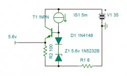
The jfet-bjt configuration is the Sony curent source, used in the Esprit series. It is temperature stable because the jfet and the bjt converge to a thermal equilibrium. An extra voltage source is in line to protect this circuit for to high rail voltages (but in this example only +/-15Vdc). The mirrors on these rails provide currents for the input differentials and, of use in your circuit, two symmetrical currents into two (as they are also called 'rubber') zeners. Instead of connecting them to powerzero, connect them to the output of the amplifier. An advantage is the very nice startup and shutdown sequence (no inbalances). Also, by manipulating the resistor connected to the b and e of the current source bjt, there is full control of the amount of current from this source, and can be used for protecting and/or those startup/shutdown sequences of the amplifier. The larger the resistorvalue, the less current results; maximum current depends on the jfet however, so limited and no runoff anyhow.
Attachments
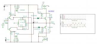
I made a quick trial for you. in sports version, I applied about 40db NFB but the distortion 20k 19v got just a single zero to be 0.09%. The culprit must be my error amp "a la Kokoriantz" which has a distortion of only 0.15% but as it is the corrector , it is correcting wrong . Some more adjustments necessary for the bias.
To have isolated low noise supply of small power , nothing is better than solar cell lit by Led light. You can even feedback by current sense to servo adjust the light intensity.
To have isolated low noise supply of small power , nothing is better than solar cell lit by Led light. You can even feedback by current sense to servo adjust the light intensity.
Attachments


I have forgotten bootstrap on the negative. Once rearranged , Now I have 0.015% always 20khz 20Vp. I think I will stop here with this amplifier. I see there are a great number of followers this thread , by owing respect , I will resume back to original theme . I think Ian ,you should now start I new thread for your amp , where besides me ,others can also help you.
Attachments
Last edited:
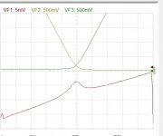
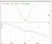
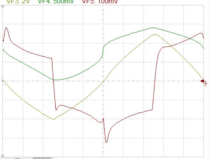
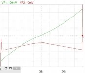
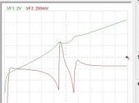
Good morning Ian. I have bad news for you. I measured the linearity of the output conductance for your non-switching technique , great disappointment .
I even didn't need to scope with the derivative function. See it yourself .
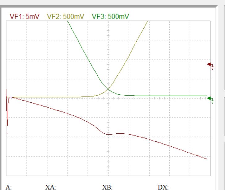
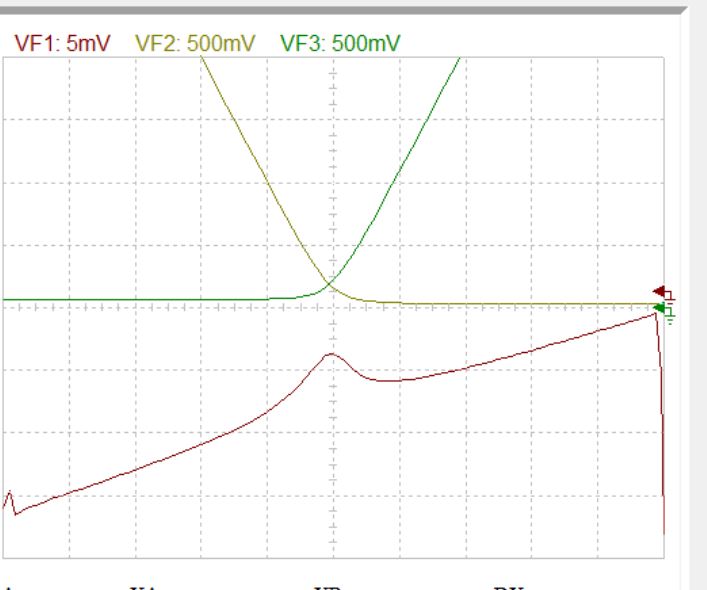
These are with Japanese, below are with NJW s.
I feel truly sorry.
Hayk
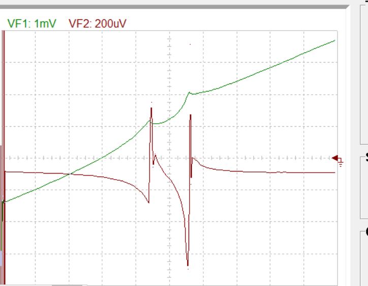
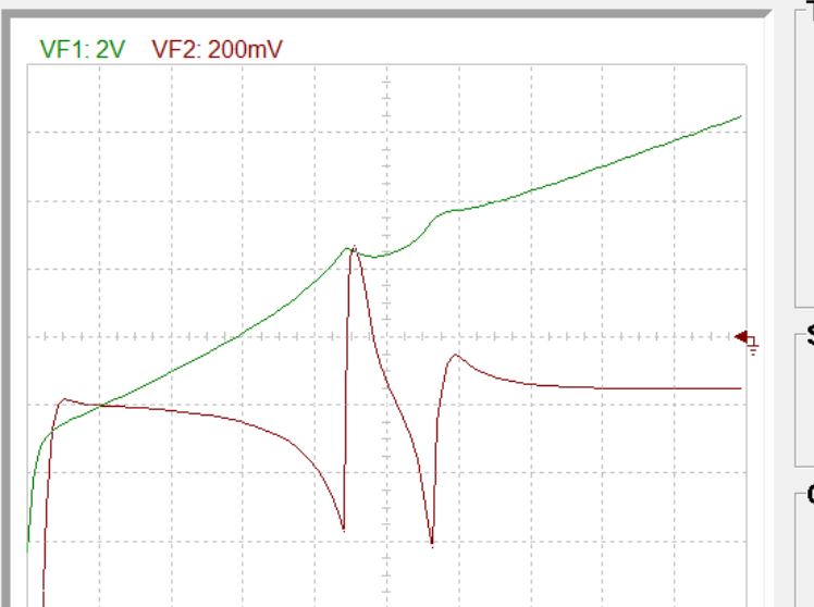
I even didn't need to scope with the derivative function. See it yourself .
These are with Japanese, below are with NJW s.
I feel truly sorry.
Hayk
Attachments
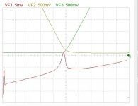
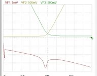
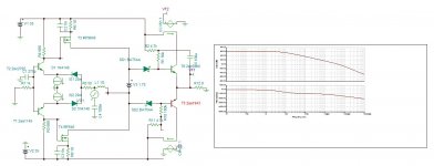
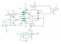
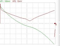
Why it doesn't work? The principle of your circuit is the high impedance current source, will over come the impedance variations of the base circuit. But, it doesn't ,because the current source by the driver collectors are limited in frequency due to dominant pole. So the switching of the fast Schottky diodes become slow. By this as the bad mouths were accusing to have switching diodes instead of transistors, got reason. I tried in most ideal condition with infinite slew rate source , even so, as you see on graph bellow it is not fast enough.
Attachments
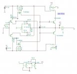
The optimal biased 3EF (2-3 pairs of njw0281g/njw0302g, 40-50V psu) is better and simpler than this non-switching OPS.
Hello LKA. Thank you for proposing these transistors . The datasheet says more linear than the NJW3281/1302, but I see the contrary. How much bias per transistor do you apply?
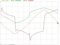
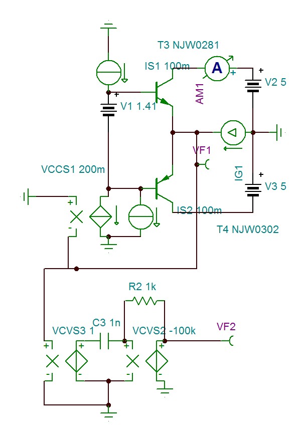
I made a test bench to test the output conductance of power transistors . Within this week, If anyone want me test his/her BJT/MOSFET, just post me the spice models or where I can download , and I'll test it for you at your desired rails/bias, with 5Ap triangular 10khz. Here is the NJW0281/302 biased 150ma +/-5v.
These transistors have clean crossover region but the transfer function is square root . The bias is about 150ma.
Hayk
These transistors have clean crossover region but the transfer function is square root . The bias is about 150ma.
Hayk
Attachments

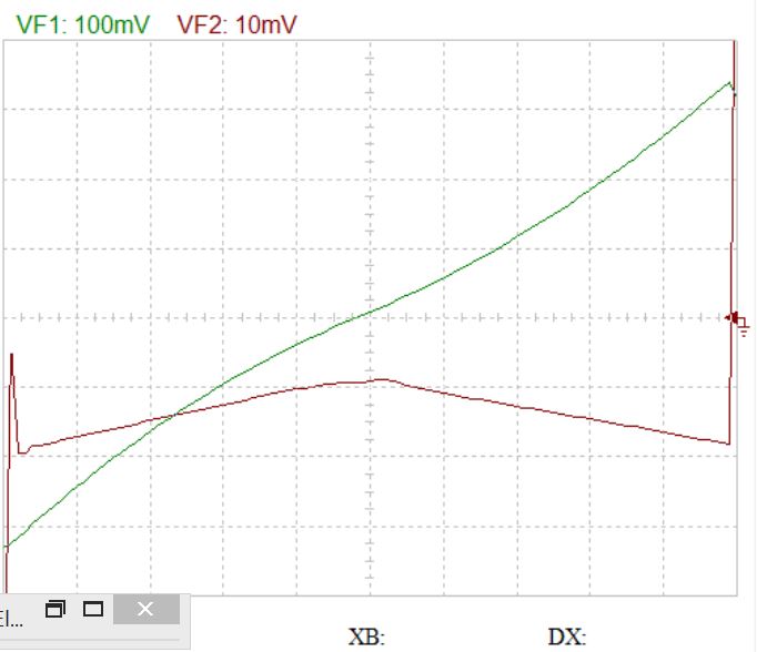
K1058/j164
This is the K1058/j164 conductance biased 177ma. Remark , besides cross over that it is linear .
in open loop
This is the K1058/j164 conductance biased 177ma. Remark , besides cross over that it is linear .
in open loop
Attachments

Last edited:

Hello LKA. Thank you for proposing these transistors . The datasheet says more linear than the NJW3281/1302, but I see the contrary. How much bias per transistor do you apply?
Class AB, 60-80mA per pair.
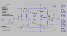
The measured performance is very close to the simulated.
I measured this configuration:
* 3EF open loop
* PSU +-50V
* predriver KSC3503,KSA1381, 1 pair
* driver 2SC4793,2SA1837, 1 pair
* output NJW0281G,NJW0302G, 3 pairs (rated power 200W/4R)
Attachments

TTA1943-TTC5200 (or eqv.) at various bias currents: 100mA, 200mA, 500mA, 1000mA.
Curious how distortion varies with the bias settings. Rest of circuit and settings as you like.
Curious how distortion varies with the bias settings. Rest of circuit and settings as you like.
Where I can find the spice models. I tried this pair in square law. If the C5200/A1943 needs 900ma , the TT version worked At 500ma.
Your post #77 is conflicting: how can you state that the 2SA1943-2SC5200 needs a different current compared to the TTA1943-TTC5200, and ask for spice models of them (2S-- vs TT--)? Why do the 2S-- needs 900mA and the TT-- 500mA??? They are from a different foundry, but the recipe and menu are the same.
I cannot provide (your) spice models: I'm from a different generation and use Aimspice, and have to model active elements therein according to the specs myself. Although the same semi models are used (Gummel Poon), the format of the model is not or hardly interchangeable. I have no experience or knowledge of current simulators. Even more, to me all simulators are just digital assumptions; the best test is a real build with the unpredictable surprises included. Simulators provide a proof of concept only, not the last word. The 1943/5200 combo is very popular on this platform (and with good reason!), so I hope another member can provide you with accurate or suitable models.
I cannot provide (your) spice models: I'm from a different generation and use Aimspice, and have to model active elements therein according to the specs myself. Although the same semi models are used (Gummel Poon), the format of the model is not or hardly interchangeable. I have no experience or knowledge of current simulators. Even more, to me all simulators are just digital assumptions; the best test is a real build with the unpredictable surprises included. Simulators provide a proof of concept only, not the last word. The 1943/5200 combo is very popular on this platform (and with good reason!), so I hope another member can provide you with accurate or suitable models.
Last edited:
More than a decade ago I designed a two stage QSc style Transnova if you prefer square law biased 50w amp that I consider it as class A . When one pole is pouring 4A , the other is still dealing with 5ma. The biasing of such circuit implies to operate exactly at the knee of IC/Vbe where the impedance is half the Re of the transistors . The knee for C5200&Co is situated at 900ma, measured in real world , where as TTA&Co was 500ma. If I chose the first , because my two stage amp made of a differantial pair of MOSFET biased 250ma , and the complimentary output in cascode , needed very high beta to provide sufficient damping factor . The TTA&Co I bought 2 pairs measured beta of less than 90 at 30°C , but vary narrowly matched, whereas the C5200&Co as the merchant allowed me to select by measurement , I could found many above 140 , even from a lot of 5 such pairs , I could get a pair of 164/162 at 30°C.
Personally , I am adept of St Thomas , I believe on what I measure. Simulator models give only a guide line how to proceed in real world. I give you a simple example. The BD139 used as voltage follower to supply as low impedance source of 5v biased at 100ma. In real world I measure the impedance 0.2ohms , the simulator measures 0.55ohms , of course sim gamers will refuse to believe as their scores would worth nothing.
Personally , I am adept of St Thomas , I believe on what I measure. Simulator models give only a guide line how to proceed in real world. I give you a simple example. The BD139 used as voltage follower to supply as low impedance source of 5v biased at 100ma. In real world I measure the impedance 0.2ohms , the simulator measures 0.55ohms , of course sim gamers will refuse to believe as their scores would worth nothing.
Last edited:
Hi Hayk,... I will resume back to original theme . I think Ian ,you should now start I new thread for your amp , where besides me ,others can also help you.
OK, back to the original theme. I assume you mean the circuit of post 1.
I have another variation of the original circuit. Would you like it posted here?
Cheers
- Home
- Amplifiers
- Solid State
- Non-switching complimentary output stage