But holy grail... Lets keep our fingers crossed...Singleton outputs are a tad inefficient for my tastes
No, only the most hardest of the hard hardcore, THS4021, AD8067, LM7171, LT1222.You could probably go single EF after e.g. an OPA1656
There are no way to override their huge feedback depth while you are familiar with proper compensation techniques.
*attached*
200 mA @ +/-15 V would mean frying away a solid 6 W per channel
The winter wasn't cold this year, so, yes, we could talk about push-pull or even AB-output.
So by the time you decide to go with something BUF634-ish, you better know how to keep supply inductance down. Really, there are many different ways of tackling this particular problem.
Ok, EF-1 could be easily changed to BUF634 or even, with some tweaks, to LT1210. Supply rails could be decoupled with solid-polymer caps.
It would be interesting to know what kind of input signal and noise levels we are dealing with and what desired output noise levels are.
Moreover, we really need at least 4 differently optimized designs.
1. For ultrahigh sensitivity armature headphones with low impedance (10-32 Ohm)
2. For high sensitivity and moderate impedance common dynamic (16-64)
3. For high sensitivity and high impedance dynamic (300-600)
4. For low sensitivity and low impedance (16-64)
First pair could run at moderate 8-12 V rails while first could demand something like -20 dB gain instead of +6dB of second.
Second pair are better to have bridged output and something like THS4131 as input while third needs +12+18 dB instead of last fourth could demand even +26 dB.
Attachments
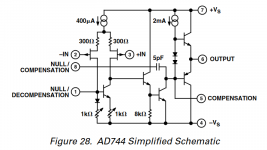
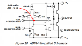
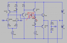
I'm fairly sure (Scott will confirm) that the schematic has an error. The pin8 connection should go to the right JFET drain and the 5pF. So to get unity gain stability another 5pF is placed in parallel with the internal 5pF. In short, there's a dot missing where the wires cross.
A "simplified schematic" can be mainly fiction - they have their intellectual property to protect, treat this as a rough guide to circuit topology only unless you have a set of die-photos at hand to check against...
Maybe Scott csn explain :
I do not quite understand how connecting pin 8 to pin 5 would make it unity gain stable.
Aren't the 2 pins already internally connected, as shown ?
Thx,
Patrick
Yes that error (don't know when it appeared) would not have been deliberate because the schematic is already very simplified. The data sheets were done back in the day with stick on symbols, tape, and stat text.
BTW it's sad that most places no longer appreciate all the access to the innards.
Last edited:
Just for fun
50 pf is a really good joke!
Let's compete?
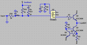
The goal will be to remove that ugly cap and achieve as much loopgain as possible at 20 kHz while keeping amp schematic and biases.
Sorry, I don't get it.
There are a bazillion really, really, really good chip-based op-amps out there; moreover, there are a few testers that have taken at least some of these op-amps and tested the hêll out of them in 'ladder-of-them-to-see-how-bad-they-are' layouts.
Sure, there is an intellectual challenge in designing an operational amplifier from discrete components; then another challenge to cherry-pick components to exacting matching standards, then another to gin up eensy little circuit boards, and solder everything (super-competently!) to them, capped off with the intellectual challenge of then testing a raft-load of the things, to measure the supposedly-superior characteristics.
Heck, except for the FT degradation, noise pickup and capricious device-heating-instabilities of laying everything out on a standard engineering socket-board strip, one really can cobble together something in an hour or two, and run up tests immediately. This I've done some decades back, driven by the same intellectual curiosity.
With all the blessings of a 50 MHz quad-channel oscilloscope, and having ginned up 10 well-matched parts discrete op-amp eensy-weensy boards, I found that none of them had characteristics superior to any of the handful of “better chip amps” I purchased some time before the enterprise.
So… again, as my uncle would say, “what's the poin?” (sic: no T)
⋅-=≡ GoatGuy ✓ ≡=-⋅
> Sorry, I don't get it.
You don't realise that it is fun, I guess.
DIY is only about fun, for me at least.
Cheers,
Patrick
You don't realise that it is fun, I guess.
DIY is only about fun, for me at least.
Cheers,
Patrick
1. To have fun
2. To listen for myself, and to form my own opinion about which options please me the most. The measurement results others achieve, and the listening impressions others prefer, are not of gigantic significance to me.
2. To listen for myself, and to form my own opinion about which options please me the most. The measurement results others achieve, and the listening impressions others prefer, are not of gigantic significance to me.
> the listening impressions others prefer, are not of gigantic significance to me.
If it is for my own use, yes.
But sometimes, for pure fun, I do things that I would not be doing for myself.
UDNeSS is a perfect example.
A discrete AD744 also.
🙂
Patrick
If it is for my own use, yes.
But sometimes, for pure fun, I do things that I would not be doing for myself.
UDNeSS is a perfect example.
A discrete AD744 also.
🙂
Patrick
And unity gain stable without any caps ?
Yes, let it be as challenge at unity gain stable and inverting connection!
No, not without any caps, but without any cap at the C1 position of yours schematic.
Only external circuitry relative to the shown opamp structure.
Just a simulator compete for curiosity how and how much...
PS
Oh, yes, and let's add aperiodic step response at, say, 2 Volts input square wave.
PPS
Also i'ld set R1&R2 smaller, say 22 Ohm and R5 say 1k for making things even complicated.
Attachments
Last edited:
An opamp which is "universally" applicable in a any existing circuits would not required external compensation.
At least that wouold be my goal.
Patrick
At least that wouold be my goal.
Patrick
Nuts it, that does.> Sorry, I don't get it.
You don't realise that it is fun, I guess.
DIY is only about fun, for me at least.
Cheers, Patrick
Thanks.
⋅-=≡ GoatGuy ✓ ≡=-⋅
An opamp which is "universally" applicable in a any existing circuits would not required external compensation.
No-no, nothing about "universally" applicable.
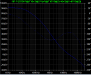
That's nonsense with something having at least 120 dB gain at 10 kHz.
This is really beast to be tamed anyway.
So, let's try? For curiosity, of course!
Well, if one has a goal of applying to existing circuits as a drop-in “better” (or at least more-easily-talked-up) replacement, then by definition, it can not be engineered to not need compensation.An opamp which is "universally" applicable in a any existing circuits would not required external compensation. At least that would be my goal. Patrick
Because … many an existing circuit, having used op-amps with parametric compensation will have chosen the best compensation values, and have them in-circuit.
Dropping in a device with 'universal' compensation changes the existing design's criteria-base!
⋅-⋅-⋅ Just saying, ⋅-⋅-⋅
⋅-=≡ GoatGuy ✓ ≡=-⋅
1. To have fun
2. To listen for myself, and to form my own opinion about which options please me the most. The measurement results others achieve, and the listening impressions others prefer, are not of gigantic significance to me.
I agree wholeheartedly with № 1.
And № 2 is equally defensible.
One thing's for sure — and that is that the string-of-modest-gain op-amp testing methods (along with a quad channel scope's marvelous comparative functions) quickly and visually identifies op-amp non-linearities. That, and a very, very pure sine-wave signal generator.
Best of The Art to you, friend.
⋅-=≡ GoatGuy ✓ ≡=-⋅
You can soup up an AD744 with a discrete output stage which is much less complexity of build than going full discrete. Assuming that the noise of AD744 isn't a show-stopper.
How would a discrete output stage be done? For example the Topping A30 has an LM337D2 going to the output RCA's. Would that be considered a discrete output?
Also, can an OPA627 with a BUF634 be replaced with an AD744 for better noise, distortion while still using a discrete output to drive big loads like 300 ohm easily? I've been thinking about paralleling 4 of them but it's not exactly cost effective.
Thanks guys
- Home
- Amplifiers
- Solid State
- Discrete op amp