Hello
The 2A fast blow fuse for the right speak blows as soon as the amp is turned on. The left channel is fine and both speaker work fine on that channel.
With the speakers and inputs unplugged the fuse is fine but as far as problem solving goes I am unable to get any further. I do understand something about electronics though and can solder so would like to see if it something I can fix with help.
The service manual with schematics is attached.
Many thanks in advance!
Attachments
I agree with John ... probably a blown output or driver.
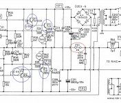
From the thumbnail... if it is blowing the fuse circled in red it is most likely one of the transistors circled in blue.
Start with nothing connected, no inputs and especially no speakers... check the voltage on the fuse itself, you should see just a few millivolts with no signal.
The schematic is marked with voltages so you can check with your multimeter to find which are wonkey. Also the blown transistor will probably be very hot.
Attachments
hijack! 
I've an alpha three with both speaker fuses blown, The output transistors are ok. I replaced the fuses and tested dc on speaker output and it spikes up to 35v on switch on then settles down to very low mv. The power diodes measure very peculiarly, they seem to take an age to 'recover' could this be why there is that spike?
I've an alpha three with both speaker fuses blown, The output transistors are ok. I replaced the fuses and tested dc on speaker output and it spikes up to 35v on switch on then settles down to very low mv. The power diodes measure very peculiarly, they seem to take an age to 'recover' could this be why there is that spike?
hijack!
I've an alpha three with both speaker fuses blown, The output transistors are ok. I replaced the fuses and tested dc on speaker output and it spikes up to 35v on switch on then settles down to very low mv. The power diodes measure very peculiarly, they seem to take an age to 'recover' could this be why there is that spike?
A turn on spike is not abnormal, they generally happen because the various capacitors in the circuit charge at uneven rates.
Define "recover"... and what kine of behaviour are you noticing from the power diodes?
A turn on spike is not abnormal, they generally happen because the various capacitors in the circuit charge at uneven rates.
Define "recover"... and what kine of behaviour are you noticing from the power diodes?
I'd imagine if 35v threatened the speakers you'd hope the fuses would do their job! The 4x 1n5404 diodes are slow to measure correctly in either direction
I'd imagine if 35v threatened the speakers you'd hope the fuses would do their job! The 4x 1n5404 diodes are slow to measure correctly in either direction
If you are measuring in-circuit don't forget you've got some pretty big capacitors right there.
Have you tried replacing them?
Also check your voltage rails with the amp turned on and no load.
Last edited:
So the latest on this is that I hit a bit of a roadblock trying to do this myself and so took the amp along to a local restart.org fix it session along with the service manual, Douglas's diagram and comments from both Douglas and John.
We identified the four transistors however rather than doing the voltage testing as suggested the guys there decided to remove the transistors and test them one by one. They seemed to think that Q14 was the problem (actually labelled Q114 on the right channel) however they weren't totally sure. I said that I would check myself therefore and order a new one if it proved to be bad.
The problem I am having however is that the markings on the transistor don't tally with what's on the schematic. On the transistor itself the markings read - AAR2955X 9316 - but on the schematic it is labelled as TIP2955. I've tried searching using the transistor markings but nothing appears to be coming up that matches.
This is link to an image of the transistor as I wasn't able to insert - Dropbox - 1.JPG - Simplify your life.
If somebody can help me identify it as the next step that would be great.
Thanks!
Many power semis are marked with "house codes" rather than standard industry part numbers. That identifies them as specially selected, grouped or differently specified to match each other and/or meet the performance specs of the model. They could also be the part numbers of other manufacturers making copies or similar products which are not to the exact same spec. Another possibility with the Alpha 3 model, is that it had higher supply rails than others in series, at +/- 38VDC. For reliability, the output transistors would probably have needed a higher Vceo rating than just 60V.
Its a guess but I think that part number derives from AR for Arcam and 2955 from the original TO3 format 2N2955 transistor. A TIP prefix would have meant they were exclusively products of Texas Instruments or its subcontractors. Otherwise, at the time it could have been an illegal use of trademark in the US at least. 9316 is just a batch/date code and you should find that on all genuine semis supplied by the OEMs.
So, we just have another manufacturer supplying similar product that may be to different spec. or perhaps the same spec as TIP2955. It's unlikely that you'll be able to buy those particular original products but ARCAM should have records of the spec. or at least tech. advice as to what to use for replacements if indeed anything other than bog-standard TIP2955 should be used.
Thanks Ian. That's very interesting and helpful information. I will certainly contact Arcam tomorrow but in the meantime I am curious to test to this one to see if it is faulty.
From what I understand is it correct I can assume this is a TP2955 for the purposes of testing at least? If so then the pins looking from the 'front' i.e. the side with the writing on are (from left to right BCE) according to this datasheet - https://alhkma.com/content/Transistors/BP/TIP2955_.pdf
The question then is what would be a definitive test. Any pointers on that would be great!
Many thanks
Many power semis are marked with "house codes" rather than standard industry part numbers. That identifies them as specially selected, grouped or differently specified to match each other and/or meet the performance specs of the model. They could also be the part numbers of other manufacturers making copies or similar products which are not to the exact same spec. Another possibility with the Alpha 3 model, is that it had higher supply rails than others in series, at +/- 38VDC. For reliability, the output transistors would probably have needed a higher Vceo rating than just 60V.
Its a guess but I think that part number derives from AR for Arcam and 2955 from the original TO3 format 2N2955 transistor. A TIP prefix would have meant they were exclusively products of Texas Instruments or its subcontractors. Otherwise, at the time it could have been an illegal use of trademark in the US at least. 9316 is just a batch/date code and you should find that on all genuine semis supplied by the OEMs.
So, we just have another manufacturer supplying similar product that may be to different spec. or perhaps the same spec as TIP2955. It's unlikely that you'll be able to buy those particular original products but ARCAM should have records of the spec. or at least tech. advice as to what to use for replacements if indeed anything other than bog-standard TIP2955 should be used.
The TIP2955 is PNP. A basic test is as follows, however most power devices like these fail short circuit which this will show.
If you have a typical digital meter switch to the 'Diode Test' range and then put the black lead on the middle pin. You should get an open circuit reading touching the red lead to the other two pins.
If that is OK then place the black lead on the 'Base' which is the left hand pin. You should now read between 500 and 700 on the meter when reading to the other two pins... and this is actually the meter reading forward voltage in millivolts.
This thread covered a lot of ground:
Arcam Alpha 3 Left Channel broken...
Arcam Alpha 3 Left Channel broken...
Thanks Mooly. I followed your very clear instructions exactly as described and got the results predicted. The reading was 1 in the first scenario which I assume means 'open circuit' and in the second I got a reading of 650.
Does this mean this transistor is OK?
Does this mean this transistor is OK?
The TIP2955 is PNP. A basic test is as follows, however most power devices like these fail short circuit which this will show.
If you have a typical digital meter switch to the 'Diode Test' range and then put the black lead on the middle pin. You should get an open circuit reading touching the red lead to the other two pins.
If that is OK then place the black lead on the 'Base' which is the left hand pin. You should now read between 500 and 700 on the meter when reading to the other two pins... and this is actually the meter reading forward voltage in millivolts.
Great thanks. Not seen this.
This thread covered a lot of ground:
Arcam Alpha 3 Left Channel broken...
Thanks Mooly. I followed your very clear instructions exactly as described and got the results predicted. The reading was 1 in the first scenario which I assume means 'open circuit' and in the second I got a reading of 650.
Does this mean this transistor is OK?
It probably is OK, but its not definitive. Most devices fail with a very low resistance or short circuit between C and E.
On the diode range the best 'open circuit' reading you can hope for is the same as you see when the probes aren't touching anything. It is meter dependent and could 1.999 or 3.999 etc which is just the open circuit voltage the meter provides for the diode range.
For faultfinding your amp I would say that careful voltage checks should get most of the way. All the evidence will be there and it becomes a matter of interpreting the readings to isolate the problems.
Thanks Mooly. Yes I was rather hoping that when I took it to the fixit group they would follow the process that Douglas had suggested i.e. testing in circuit voltages. Instead they rather rashly I feel removed the four potentially suspect transistors without it seems really knowing how to properly test them. Anyway you live and learn. Next time I will insist that the diagnostic steps as provided by people who clearly do know what they are talking about are followed precisely.
The thread you sent earlier is a case in point. Very impressive and a model of how it should be done.
The thread you sent earlier is a case in point. Very impressive and a model of how it should be done.
Taking matters back into my own hands I am keen to get guidance on how to starting taking readings safely however I do of course realise this might require too much hand holding so I'm quite prepared for that being too much trouble.
Douglas's suggestion was to first 'check the voltage on the fuse itself' however I am not clear how to do that. Obviously I know to set the DM at the appropriate setting however I am unclear as to which points I should be touching the probes in to take the reading.
Douglas's suggestion was to first 'check the voltage on the fuse itself' however I am not clear how to do that. Obviously I know to set the DM at the appropriate setting however I am unclear as to which points I should be touching the probes in to take the reading.
I would recommend first rigging the amp up with a DBT (dim bulb tester) which does prevent lots of current flowing under fault conditions. That is just a 60 or 100 watt mains filament lamp in series with the live feed to the amp.
With the amp all back together you put the meter negative lead onto ground which will almost certainly include the metal chassis.
First checks are always supply voltages, we never assume anything without confirming it to be correct. With a bulb tester in circuit the voltage will be a little low (assuming nothing is drawing excess current) and so you should read PLUS 38V on the collector (middle pin) of the TIP3055 and MINUS 38V on the collector of the TIP2955.
It might be easier and safer (we don't want any slips of the probe) to measure on D3 and D4 instead... look at the circuit and you will see they are the same points.
Next measure the voltage on the speaker fuse. That should be close to zero but won't be with your fault.
Switch the amp OFF and check those two 0.22 ohm resistors. You can test those in circuit but remember they are so low in value that your meter lead resistance will add to the result. You should see 0.4 ohm or lower for each.
Next we put the black lead of the meter on the speaker fuse (you can connect it to the positive speaker socket if the fuse is intact) and then we take four readings with the power on.
1/ To the base of the TIP3055. You should see approx +0.6 volts.
2/ To the base of the driver Q11. You should read approx +1.2 volts.
3/ To the base of the TIP2955. You should read approx -0.6V
4/ To the base of the driver Q12. You should read approx -1.2V
For all faultfinding you have NO speakers attached.
- Status
- This old topic is closed. If you want to reopen this topic, contact a moderator using the "Report Post" button.
- Home
- Amplifiers
- Solid State
- Arcam Alpha 3 right channel fuse keeps blowing