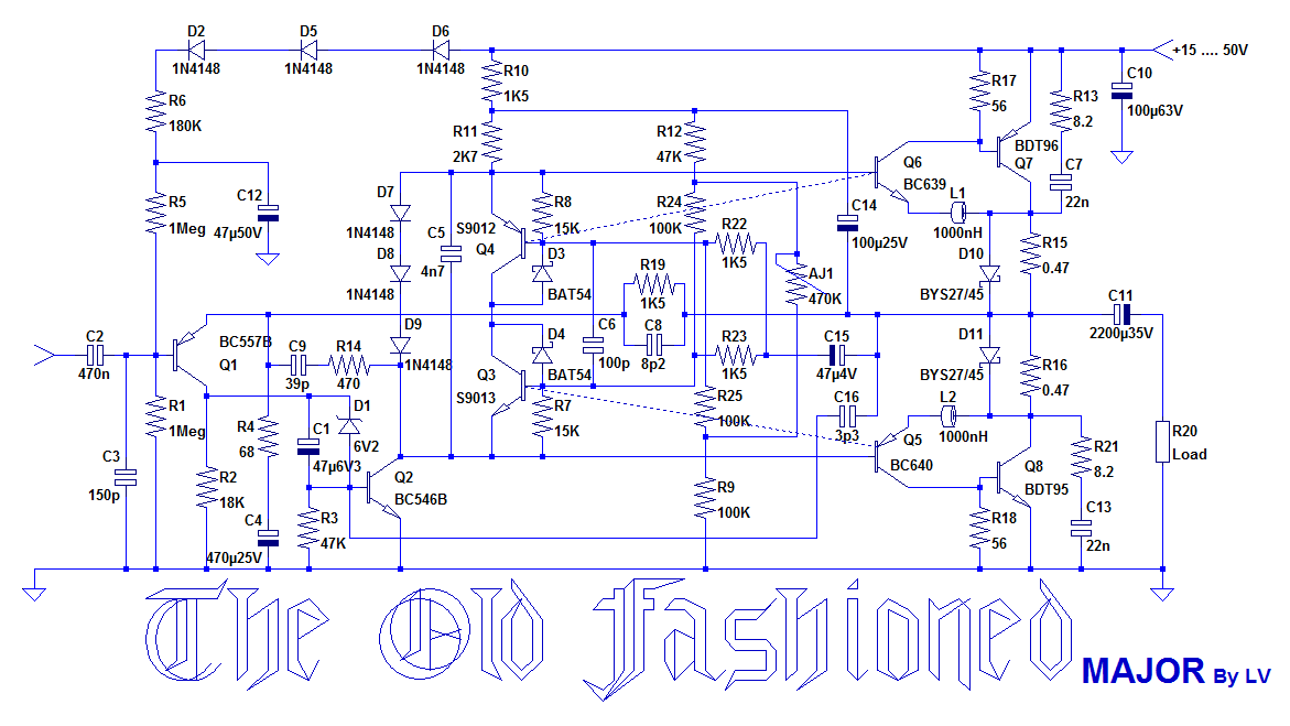
Following a request, here is the big brother of the Old-Fashioned lite:
The Old-Fashioned Major.
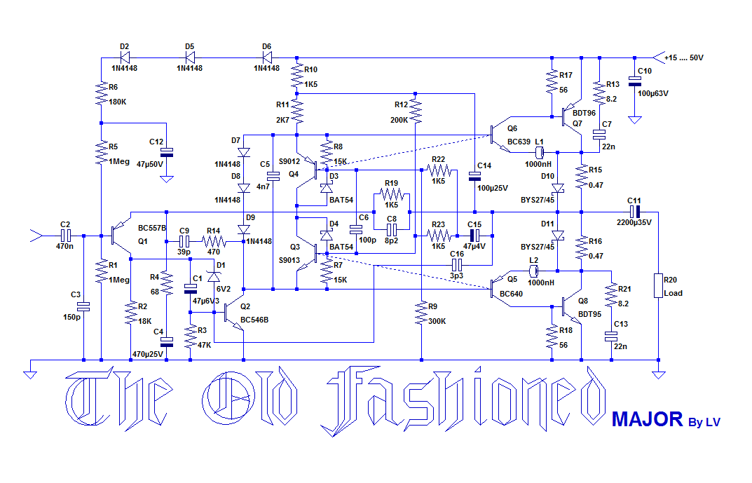
It also belongs to the series I proposed to Daniel, but it was rejected at an early stage, probably because of its messy look, both in schematic and in prototype.
It does fit the bill though: single supply, old fashioned techniques with the ease of a chipamp, transistor count <11, and good performance and flexibility.
Since it has to be as easy as possible for inexperienced builders, it also includes a smart bias scheme, making any adjustment unnecessary.
The strategy it uses is based on a completely novel philosophy:
It is neither the usual type of Iq servo, encountered for example in the EZmos, nor the trick used in the lite version, because this trick cannot be upgraded to work satisfactorily with composite OP's: in fact, the static Iq is not servoed, but a peculiar class B engine enforces a dynamic non-switching behavior, meaning the static value is essentially unimportant, and does not affect performances.
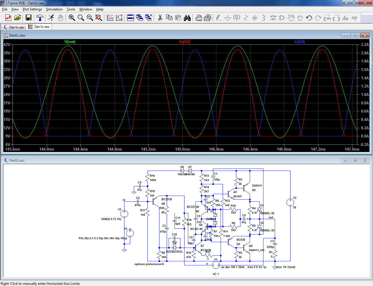
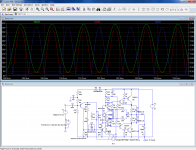
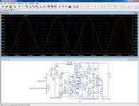
The class B engine is built with just two transistors, Q3 and Q4: without C4, they would just form a bog-standard bias spreader, as this sim illustrates (sorry, the graphic version is not functional, the sim is messy, and C4 becomes C8):
When C4(8) is in service, the class B engine becomes operative, as can be seen here:
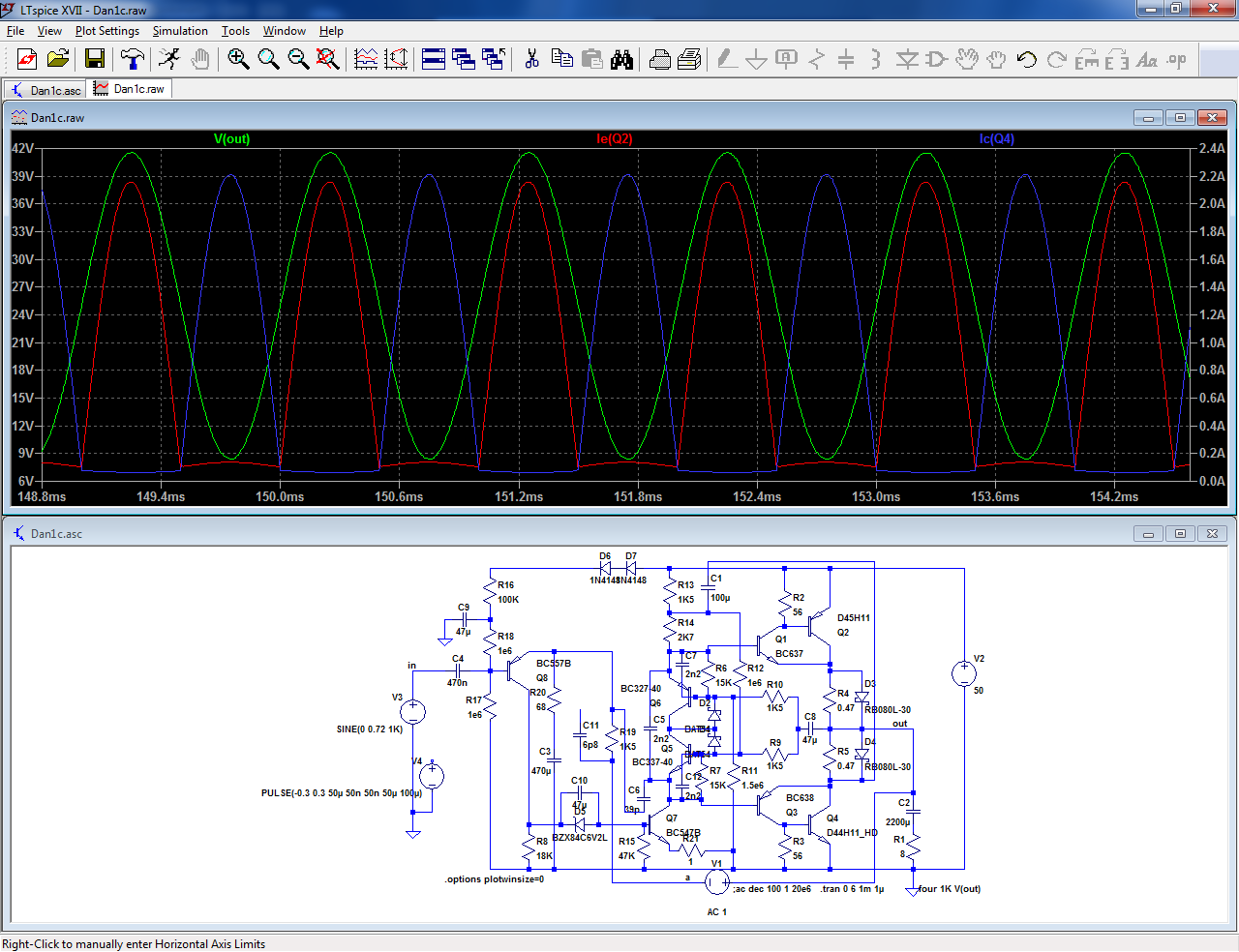
Now, all the transistors conduct all the time.
It works rather well: the measured THD @ 35W/8Ω is 0.004%, which is quite respectable for such a simplistic circuit.
It is also quite efficient, and swings to within ~1V of the supply rails.
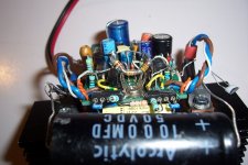
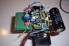
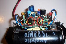
Here are some pics of the prototype(!):


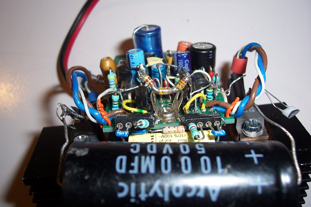
On the prototype, a BDT96 was replaced by a BD204 because i managed to fry it (how surprising!), and I had no spare.
It has experienced a number of shorts from OP to the supply rails without damage, but the sixth time was fatal....
The Old-Fashioned Major.
It also belongs to the series I proposed to Daniel, but it was rejected at an early stage, probably because of its messy look, both in schematic and in prototype.
It does fit the bill though: single supply, old fashioned techniques with the ease of a chipamp, transistor count <11, and good performance and flexibility.
Since it has to be as easy as possible for inexperienced builders, it also includes a smart bias scheme, making any adjustment unnecessary.
The strategy it uses is based on a completely novel philosophy:
It is neither the usual type of Iq servo, encountered for example in the EZmos, nor the trick used in the lite version, because this trick cannot be upgraded to work satisfactorily with composite OP's: in fact, the static Iq is not servoed, but a peculiar class B engine enforces a dynamic non-switching behavior, meaning the static value is essentially unimportant, and does not affect performances.
The class B engine is built with just two transistors, Q3 and Q4: without C4, they would just form a bog-standard bias spreader, as this sim illustrates (sorry, the graphic version is not functional, the sim is messy, and C4 becomes C8):
When C4(8) is in service, the class B engine becomes operative, as can be seen here:
Now, all the transistors conduct all the time.
It works rather well: the measured THD @ 35W/8Ω is 0.004%, which is quite respectable for such a simplistic circuit.
It is also quite efficient, and swings to within ~1V of the supply rails.
Here are some pics of the prototype(!):
On the prototype, a BDT96 was replaced by a BD204 because i managed to fry it (how surprising!), and I had no spare.
It has experienced a number of shorts from OP to the supply rails without damage, but the sixth time was fatal....
Attachments

A collection of vintage, single supply, low to medium power amplifiers for Daniel - diyAudioGot me curious sorryWho is Daniel?
Cheers!
Which amps have low parts count, single supply, and don't fry your speaker if you make one bad solder joint. Which lends it to point to point build; no PCB layout software or printer required.
Great that this concept is being updated beyond the .06% HD of the AX6.
I can acually buy BY527 with leads, but all the BAT54 at farnell US mouser US & digikey US still have no legs. 6v2 is maybe a 6.2 v zener?
Being US based I'd use MPSA56 input, MJE15028/29 as q3/q4 q5/q6 and MJL21193/94 as outputs, but that is just because I have them on the shelf. I have BD139/140 as drivers but they are fairchild without the Phillips Ft spec. The On drivers are 30 mhz ft. Any gross mismatches please highlight. Group buy on the schottky diodes North American readers?
Last edited:
BYS27, not BY527, but any large schottky will do.I can acually buy BY527 with leads, but all the BAT54 at farnell US still have no legs.
I didn't use a BAT54 actually, probably a BAT43, 48, 85 or similar: it does not really matter any >200mA schottky will do.
I know there is a 1Nxyzz type too, but I can't remember the exact type N°.
Can someone help?
MPSA56 is OK, MJE15028 is much too large (it will work though): opt for something more reasonable, in TO92 or TO126 at most (even Fairchild's), or a good old TO5 like 2N2905 and 2N2219Being US based I'd use MPSA56 input, MJE15028/29 as q3/q4 q5/q6 and MJL21193/94 as outputs, but that is just because I have them on the shelf. Any gross mismatches please highlight. Group buy on the schottky diodes North American readers?
Basically the design is undemanding: you need to respect basic Vceo, Icm, Pdmax and SOA ratings but that's about it
Last edited:
For North-American members, the MP-- series has all the types needed for the signal part: MPSA, MPSL for the low level and general processing, MPSW for the drivers.
The 2N series also has an infinity of suitable types (don't mix Ge with Si types though).
The S9--- series originally from Fairchild will also work, even cheap chinese versions (my prototype uses two of them).
Of course, the 2S series also has plenty of suitable types.
Don't go overboard though and use types with 2GHz Ft: that's asking for trouble and won't bring any benefit
To summarize:
The purpose of the amplifiers designed for Daniel (EZmos, Oldfashioned) is to offer a decent performance level with dubious or even crap components, combined with minimal or zero adjustment.
Don't push it too far though: for example using a 2N3904/6 pair as OP will lead you straight into a wall...
Last edited:
Ha, newark (farnell US) & digikey have BAT48 a 350 ma 400 mv schottky diode with leads, from ST.
BYS27 is not available from farnell US, digikey, mouser, nor does datasheetcatalog.com have a sheet for it. What back voltage min, what working current, what vf @ what current were you expecting? You reacted in horror when I suggested subtituting the ON semi 100 piv 1 A schottky diodes I have for the bat54 in the oldfasioned.
I've tried to buy 2n2019 2n2905 TO5 parts since I found the burned ones in the dynaco ST120 ~1985. The single survivors I have are driving the best sounding amp channel I have (ST120) with the djoffe 7 transistor bias control circuit addition, but NTE49/50 (TO220) and TIP41c/42c are sluggish substitutes (on the AX6 board) that don't have as good high frequency IM distortion. Hence my fascination with Ft, which is unspecified for NTE49/50 and is 3 mhz for TIP41c/42c. BD139/140 is thrown around a lot on here as drivers, but the specless fairchild parts we can buy here may be nothing like the phillips originals.
I got 100 MPSW56 2.5 watt TO92 in the great ON semi phillipines fab closeout, but matching MPSW06 are available only from a surplus house. They are not ON semi parts and though I bought some, I don't trust them. I bought some newark 2n5682 TO39 parts (metal can) 10W 120 v to complement the MSPW56 as drivers, they do have a 30 mhz ft, but the QA is all farnell. Who knows how quiet they are? At least they will take a heat sink.
I trust the MJE15028/29 from farnell to be real & fast, they have a nice heat tab in TO220, but Cob may be high.
Last edited:
The BYS27 can be replaced by any 3A schottky: 1N5820--->22
The input transistor can be any PNP low power, >30V, >100mA, say 2N4403
The VAS can be a 2N5551
2N4401 & 2N4403 for the class B engine
The Fairchild BD's are OK as drivers (the MJE15028, 29 are overkill but they will work too)
The MJL's will obviously work as OP.
A word of caution: of the three projects (EZmos, Old Fashioned lite, and Major), the Major is the less mature.
EZmos has been refined and studied in depth and is completely mature, the OF lite has received a bit less attention, and the Major has been rejected very early, meaning some aspects may still need to be explored and discovered.
Thanks, the rains of October will be here before I attempt this.A word of caution: of the three projects (EZmos, Old Fashioned lite, and Major), the Major is the less mature.
EZmos has been refined and studied in depth and is completely mature, the OF lite has received a bit less attention, and the Major has been rejected very early, meaning some aspects may still need to be explored and discovered.
Love your compact point to point build, true DIY.
Thanks for the in stock parts translation.
I suppose the dotted lines mean the class B engine transistors are screwed to the heat sink with the output transistors? I was thinking MJE340/350 or BD139/140 in stock for those, they have a heat pad. Although the 250 mhz Ft of 2n4401 might be important. I have 150 mhz MPS8099 KSC1845 & KSA992 if the Ft is more important than the heat sense pad.
I already put an 8 turn SMPS inductor series the wire back from the heat sense diodes to VAS on the AX6 to prevent oscillation.
I'll be putting on 70 v rail, to replace poor HF response AX6 with TIP41/42c drivers (now banging due to bad solder joint). I'll probably increase R11 and R17,18 values a little bit to cope. Also heat sinks on everything but input trans.
Low wire count rocks for point to point builds.
Last edited:
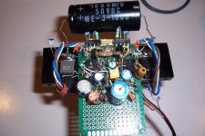
The primary thermal connection is between the engine transistors and the drivers (because of the CFP OP): they are in direct contact, as I tried to highlight on this pic (not very visible, the epoxy of both is black).I suppose the dotted lines mean the class B engine transistors are screwed to the heat sink with the output transistors? I was thinking MJE340/350 or BD139/140 in stock for those, they have a heat pad.
A secondary thermal connection is made with the OP transistors, via a metal standoff and the two solder tags, also visible on the pic.
It is probably not necessary to exactly observe this construction, but the hierarchy of the couplings is correct, and should be kept in mind when planning the layout/building.
The Ft in this case is almost irrelevant, thermal contact is very relevant.Although the 250 mhz Ft of 2n4401 might be important. I have 150 mhz MPS8099 KSC1845 & KSA992 if the Ft is more important than the heat sense pad.
The amplifier is designed to be supply-scalable, a bit like a chipamp , meaning you don't have to change anything for higher supply, except voltage rating of caps, Vceo of transistors, etc, and in fact, you cannot change anything (in principle at least), because higher supply voltages means a higher peak current in the speakers, requiring more current from the transistors and from the drivers, so if you scale something, you should also scale the output impedance: 16 ohm for example.I'll be putting on 70 v rail, to replace poor HF response AX6 with TIP41/42c drivers (now banging due to bad solder joint). I'll probably increase R11 and R17,18 values a little bit to cope.
Of course, your transistor choices have a higher Hfe, so you could probably get away with larger resistors values, but you should check it first.
Otherwise, if you use really high voltages, you will need to increase the power rating of the resistors, and add a heatsink to the VAS, but for 70V, this won't be necessary
The class B engine does not by itself require heatsinking, because its dissipation is negligible, but as outlined above, it has to be in close thermal contact with the driversAlso heat sinks on everything but input trans.
Attachments
The SP2XT speakers are 300 W RMS (49v) 8 ohm (5.5 minimum @ crossover) so I think they will take all the current the output transistors will put out. I've gotten 25 vac avg out of the AX6 board for 5 seconds at a time, on one pair MJ15003 O.T., so I imagine the speaker cap would melt before the speaker. I just keep the gain down. Classical music has a low crest factor, & I have fans so nothing was damaged.
That power rating is why I didn't consider building an oldfashioned; the power rating was too low for cannon shots in 1812 overture even if the quiet parts are 1/4 watt.
That power rating is why I didn't consider building an oldfashioned; the power rating was too low for cannon shots in 1812 overture even if the quiet parts are 1/4 watt.
Last edited:
I took an old 1980's Maplin 225WRMS disco amplifier and changed the transistors for more modern ones. I added a DC servo and added CCS on front end. I just used two output transistors to get 100 watts RMS. It sounds very good.
An externally hosted image should be here but it was not working when we last tested it.
Dear elvee,
I had entered the file in Diptrace and enclosed. I tried to follow the schematic posted by you. There may be some mistakes. Kindly check the scheme enclosed as png. I made a few minor changes. The BJTs shown are the ones I am having. The input scheme is adopted from your "Single supply Circlophone".
Thanking you,
gannaji.
Attachments
OK, I thought the folder contained other info, like layout.
The OP transistors are quite fast compared to what I used, and you might experience instabilities, requiring some values adaptation, for example R27, 8, C14, 15, L1, 2.
R29 C16 should not be necessary, but you can include them on the PCB and leave them empty.
Many resistors do not need to have a high power rating: R25, 26 can be 0.25W.
R8, 21, 22 too.
R12 should be 0.5W.
Remain aware of this warning:
With this in mind, it might also be prudent to include the possibility of quiescent current adjustment: I do not have enough experience with this circuit to guarantee that it won't need one.
Here is how it could be implemented:
The OP transistors are quite fast compared to what I used, and you might experience instabilities, requiring some values adaptation, for example R27, 8, C14, 15, L1, 2.
R29 C16 should not be necessary, but you can include them on the PCB and leave them empty.
Many resistors do not need to have a high power rating: R25, 26 can be 0.25W.
R8, 21, 22 too.
R12 should be 0.5W.
Remain aware of this warning:
C5, C6 and C9 might need to be tweaked.A word of caution: of the three projects (EZmos, Old Fashioned lite, and Major), the Major is the less mature.
EZmos has been refined and studied in depth and is completely mature, the OF lite has received a bit less attention, and the Major has been rejected very early, meaning some aspects may still need to be explored and discovered.
With this in mind, it might also be prudent to include the possibility of quiescent current adjustment: I do not have enough experience with this circuit to guarantee that it won't need one.
Here is how it could be implemented:
Attachments

Explorer says the compressed folder is empty....
Despite the file extension, it is a RAR file. (Open in a hex editor and look at the first three characters.)
It may open on some systems via a multi-protocol unzip/rar. It may open if you change .ZIP to .RAR and your system then gets the key clue. I don't RAR so I did not go further.
OK, I thought the folder contained other info, like layout.
The OP transistors are quite fast compared to what I used, and you might experience instabilities, requiring some values adaptation, for example R27, 8, C14, 15, L1, 2.
R29 C16 should not be necessary, but you can include them on the PCB and leave them empty.
Many resistors do not need to have a high power rating: R25, 26 can be 0.25W.
R8, 21, 22 too.
R12 should be 0.5W.
Remain aware of this warning:
C5, C6 and C9 might need to be tweaked.
With this in mind, it might also be prudent to include the possibility of quiescent current adjustment: I do not have enough experience with this circuit to guarantee that it won't need one.
Here is how it could be implemented:
Thank you elvee ! I shall do modifications in the Dip file and post. Assuming the numbers you refer are as per your diagram !
A good experiment to do !
No!Assuming the numbers you refer are as per your diagram !
Yours
- Status
- This old topic is closed. If you want to reopen this topic, contact a moderator using the "Report Post" button.
- Home
- Amplifiers
- Solid State
- Old-fashioned amplifiers with a new twist (2)