Interesting, will try. Thanks.
I was trying to create a LR circuit.
Clearly in this case that isn't quite true as the L has a 100R of resistance too.
But if the inductance makes no difference in this circuit then it wont in an amplifier. The amp output is a transistor (variable resistor) in series with LR emitter resistor.
A better test would be 0r1 WW in series with 0r1 none WW.
No noticeable shift in phase, which may mean phase shift less than perhaps 10 degrees? To do this test properly you would need to do sine wave drive and X-Y scope. In either case the test shows the difference between the two resistors, not their absolute inductance.nigelwright7557 said:Very easily. I just made a potential divider with 100r metal film resistor and 100r wire wound resistor.
I put one scope lead on input and another at the connection of the two resistors and compared relative phases on the scope at 2MHz.
No shift in phase at all.
If only life were so simple! In a typical amp the emitter resistors are much lower resistance but possibly similar inductance so any inductance will have greater effect. Also, there is more to a follower than a variable resistance followed by the load. You can make a follower oscillate by adding some capacitance; a variable resistor will not oscillate.But if the inductance makes no difference in this circuit then it wont in an amplifier. The amp output is a transistor (variable resistor) in series with LR emitter resistor.
The only way to check if a particular resistor will cause trouble in a particular amplifier is to try it. Simulation is unlikely to help. Fortunately, most resistors will be fine in most amplifiers.
Last edited:
No noticeable shift in phase, which may mean phase shift less than perhaps 10 degrees? To do this test properly you would need to do sine wave drive and X-Y scope. In either case the test shows the difference between the two resistors, not their absolute inductance.
The inductance is a factor too of the collective impedance/resistance.
I was using 2MHz so any "significant" inductance at that frequency would give a high impedance. In practice it gives next to none.
I use the Isabellenhuette PBH resistors.
They're 3 watt and with heatsink 10 watt.
In the current noise resistor test doc they're the best, see page 10 figure 8, line at the bottom (zoom in the graph for better distinction in line styles)
You can buy them at Buerklin
They're 3 watt and with heatsink 10 watt.
In the current noise resistor test doc they're the best, see page 10 figure 8, line at the bottom (zoom in the graph for better distinction in line styles)
You can buy them at Buerklin
I use the Isabellenhuette PBH resistors.
They're 3 watt and with heatsink 10 watt.
In the current noise resistor test doc they're the best, see page 10 figure 8, line at the bottom (zoom in the graph for better distinction in line styles)
You can buy them at Buerklin
Interesting paper Danny,
To bad those Isabellenhuette resistors are that expensive. €6 each. That would mean over €100 for my current amplifier.
Very easily. I just made a potential divider with 100r metal film resistor and 100r wire wound resistor.
I put one scope lead on input and another at the connection of the two resistors and compared relative phases on the scope at 2MHz.
No shift in phase at all.
An externally hosted image should be here but it was not working when we last tested it.
100R resistors don't count. How much inductance do you need before it starts to make a difference to 100ohms? A lot.
1ohm and less and suddenly you don't need so much inductance to make a difference.
So your test should be done with proper emitter resistor values, such as 0.33R. I bet you'll get a different picture. But of course, long leads on the reference resistor (the known good one), and suddenly it too is inductive...
Not to drag this thread into the extreme, WW are fine in my opinion, but there are samples that are really poor, as in really inductive, and one example was shown in post 45.
Hi SemperFi,
What model of HP network analyzer are you using? I have a 4195A with the impedance measuring kit, but no stages and no APC-7 connectors to build one or more.
-Chris
4194A
We bought a modern take on this instrument a few years ago, from Keysight, but the HP4194 is always used, and the Keysight never used... it's just such a great instrument.
100R resistors don't count. How much inductance do you need before it starts to make a difference to 100ohms? A lot.
1ohm and less and suddenly you don't need so much inductance to make a difference.
So your test should be done with proper emitter resistor values, such as 0.33R. I bet you'll get a different picture. But of course, long leads on the reference resistor (the known good one), and suddenly it too is inductive...
I always thought the higher the R the more inductive a WW become since more winding is needed, this off course assuming low R and high R WW are manufactured using the same wire material, and same construction method.
Using different material might be not economical from production cost perspective.
Last edited:
Hi kecapmanis021,
The high resistance swamps out the inductance (lowers the Q a lot).
Hi SemperFi,
Nice instrument indeed.
Nothing sadder than a piece of test equipment sitting around unused and unloved.
-Chris")
The high resistance swamps out the inductance (lowers the Q a lot).
Hi SemperFi,
Nice instrument indeed.
I hear your plight though. That nasty Keysight instrument? I'll suffer using it if you want. I can see many late painful nights learning how to get around in the menus, but I would soldier through and get 'er done.... but the HP4194 is always used, and the Keysight never used
Nothing sadder than a piece of test equipment sitting around unused and unloved.
-Chris
Hi kecapmanis021,
The high resistance swamps out the inductance (lowers the Q a lot).
-Chris
Hi Chris, thanks for pointing out.
Interesting paper Danny,
To bad those Isabellenhuette resistors are that expensive. €6 each. That would mean over €100 for my current amplifier.
They're also available in large SMD package (3W) from Distrelec for about 1-2€
Regards,
Danny
Pioneer VSX-523-K Emitter Resistor Types
Hi folks,
I'm new here and I would appreciate the help. I saw a long thread regarding resistor types on the Emitter stages, and I still don't know the answer.
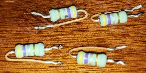
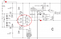
I have a blown channel on my Pioneer amplifier. Some of the bad components were 0.47 Ohm Resistors (See Schematic and photos)
I'm trying to identify the type of these resistors to replace. I see some coating on the leads of these. Can anyone tell me what these are??
Label on schematic is 0R47(2), I'm assuming 0.47 Ohm @ 2W
They look like metal oxide. Do they have to be flame proof, coated, .. ??
Thank you
Hi folks,
I'm new here and I would appreciate the help. I saw a long thread regarding resistor types on the Emitter stages, and I still don't know the answer.
I have a blown channel on my Pioneer amplifier. Some of the bad components were 0.47 Ohm Resistors (See Schematic and photos)
I'm trying to identify the type of these resistors to replace. I see some coating on the leads of these. Can anyone tell me what these are??
Label on schematic is 0R47(2), I'm assuming 0.47 Ohm @ 2W
They look like metal oxide. Do they have to be flame proof, coated, .. ??
Thank you
Attachments
Yes, 0.47 ohm. They do look like either metal oxide or wirewound type. If they have blown then the output transistors are almost certainly zapped as well. The resistors would not fail on their own.
Flameproof is part of the design brief. Often this is done because non flameproof types can burn and smell when they fail which of course can cause alarm to a customer.
It is your call what to fit although normally for this application we just use something of suitable rating and type.
https://uk.farnell.com/tt-electroni...-0r47-5-2w-axial-wirewound/dp/1219195?st=0.47
https://uk.farnell.com/multicomp/mcknp02sj047ka10/res-0r47-5-2w-axial-wirewound/dp/1903761?st=0.47
You are correct, both amplifiers were blown, resistors blown, caps popped,..
Thank you very much. I cracked one open, and it looks like it has film type material inside (solid ceramic like material)
I'd never seen coating on the leads of axial resistors before, so I'm not sure if that's critical? is it non-arcing ?
Thank you very much. I cracked one open, and it looks like it has film type material inside (solid ceramic like material)
I'd never seen coating on the leads of axial resistors before, so I'm not sure if that's critical? is it non-arcing ?
I've seen the lead coating many times in general servicing but never really thought much about it tbh. I don't think there is much significance in it tbh. It is pretty common even in 0.25 watt ratings of carbon film resistors.
They are not critical at all beyond having to be 'low inductance' but given that 0.47 ohm means only a turn or two of wire they are automatically low inductance anyway.
I would advise you to use a DBT (dim bulb tester) when initially powering up the amplifier as it can save blown devices if there is a problem anywhere.
I've seen the lead coating many times in general servicing but never really thought much about it tbh. I don't think there is much significance in it tbh. It is pretty common even in 0.25 watt ratings of carbon film resistors.
They are not critical at all beyond having to be 'low inductance' but given that 0.47 ohm means only a turn or two of wire they are automatically low inductance anyway.
I would advise you to use a DBT (dim bulb tester) when initially powering up the amplifier as it can save blown devices if there is a problem anywhere.
Thank you.. great idea on the DBT!!
Hi folks,
I'm trying to identify the type of these resistors to replace. I see some coating on the leads of these. Can anyone tell me what these are??
Label on schematic is 0R47(2), I'm assuming 0.47 Ohm @ 2W
Yes, it is 0R47 2W. It is better to use non inductive resistor here. Because inductance here can reduce phase margin so it reduce stability. I use metal film resistor.
The lead coating is generally seen on parts that are formed for stand-up insertion. It can prevent adjacent parts from shorting together if they are bent over somehow.
Thanks, I had never thought 'why' before
Right on.. these are definitely installed standing-up. I just can't seem to find a resistor with that coating pre-applied. Is it something I can do to a regular resistor?
Wire jacket over it would do the trick, or does it get excessively hot?
Does it really need it ? Once fitted they are a permanent fixture. Don't worry, just get some 0.47 ohm 2W and get them fitted
They do not get hot in normal use.
- Home
- Amplifiers
- Solid State
- Output stage emitter resistors