It is a fine voicing change but you need to try the experiment to be sure whether there is effect or not, elsewise you are just speculating and arguing, you can be sure that Pass Labs listened before deciding on the Blue Panasonic resistors.It's plausible to judge emitter resistors wrt stability, oscillations etc. But I honestly don't believe in 'voicing' of amplifiers by them, unless the same amp is unstable with WW's. That's audiophoolish BS.
Best regards!

Well, did N.P. do any DBT's with some statistically significant number of subjects?
Best regards!
Best regards!
These are about the most obviously audible resistors in an amp. If one's ears are of course inclined to hear such things. Much of the bad vibe of paralleled outputs can be attributed to crappy oxide resistors.
Fortunately sub-ohm WW resistors are not many turns and not very inductive anyway.
Well, in his book Valve Amplifiers, 3rd ed., Morgan Jones has proven comprehensively that the resistance to parasitic inductance quotient is so much better the higher the nominal resistance is. Hence he favours high wattage plate WW's over carbon's and others.
Best regards!
In what terms are oxide resistors 'crappy' ?......Much of the bad vibe of paralleled outputs can be attributed to crappy oxide resistors.
Dan.
And, of course, if one is strongly inclined to claim that DBT's aren't the right way to prove.If one's ears are of course inclined to hear such things.
Best regards!
Has ANYONE measured a typical emitter resistor L (say a 5W type) ?
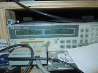
Here you are.
Attachments
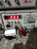
Oh no!Thimios, did you zero out the lead inductance?
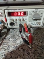
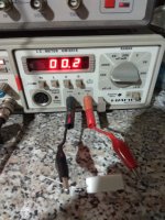
New measurement.
1)zero out the lead inductance.
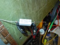
2)inductance of a common wire resistor.
3)inductance of an audio grade resistor.
Attachments
Last edited:
So excuse my ignorance but are metal film or metal oxide resistors completely non inductive?
Regards
Alan
Regards
Alan
Hi JMFahey,
The Nikko NA-100 (total POS) which used STK output ICs were completely intolerant of WW emitter resistors. The fix? Plate resistors.
I measured WW resistors a long time ago and forgot the readings. They weren't that high.
Dale CW5 0R22 @ 1KHz - 0.15uH, NTE 5W bathtub 0R22 @ 1 KHz - 0.41 uH using an HP 4263A. BTW, the 5W plate resistor under the same conditions measures 0.01 uH.
-Chris
Attachments
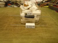
Film ones may sound better than cheap Chinese resistors with their Chinese wires. I tried to compare the sound of different resistors. The best in sound are the Soviet C5-5B https://eandc.ru/pdf/rezistor/s5-5v.pdf, which they did for military equipment, like almost everything else in the USSR. They used very high-quality wire from precision alloys.
Good films resistors even with radiators can be very expensive, in my opinion, they are produced by Vishay, AVX and similar brands.
Good films resistors even with radiators can be very expensive, in my opinion, they are produced by Vishay, AVX and similar brands.
Last edited:
Both types of film resistors, in either cylindrical or flat SMD format, are trimmed in manufacture by scribing the film variously to produce a range (generally, the E series) of standard values. The scribing, in either helical or maze-like format, also increases inductance according to the pattern of the resistive path formed for a given resistance value. However, inductance is usually quite small in low resistance types and by substituting several low power resistors in parallel, even that can be substantially reduced.So excuse my ignorance but are metal film or metal oxide resistors completely non inductive?
Thanks.Hi JMFahey,
The Nikko NA-100 (total POS) which used STK output ICs were completely intolerant of WW emitter resistors. The fix? Plate resistors.
I measured WW resistors a long time ago and forgot the readings. They weren't that high.
Dale CW5 0R22 @ 1KHz - 0.15uH, NTE 5W bathtub 0R22 @ 1 KHz - 0.41 uH using an HP 4263A. BTW, the 5W plate resistor under the same conditions measures 0.01 uH.
-Chris
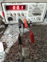
Your Dale CW5 0R22 @ 1KHz - 0.15uH, NTE 5W bathtub 0R22 @ 1 KHz - 0.41 uH measurements are in the same range as Thymio´s measurements of (presumably) 0.33 ohms - 0.2 uH so I agree with you on that.
At the same time I find that inductance value very small and significant only well beyond the Audio range.
I had already used thymios´ measurements and found (assuming 0.33 ohms) that inductive reactance reached that value at some 260 kHz, what makes me consider it minuscule within the Audio band.
I know, they are inside the loop but are neither the whole load nor the whole NFB so I find any design which is readily compromised by that, a very poor one and so not a good example that special low inductance emitter resistors are THAT critical, at least not everywhere.
Notice the short resistor leg stubs shown (clips seem to grab them about 1 cm from resistor body) *already* show around 0.1uH (since zeroing meter substracts that value) , compared to that I must find the "cheap" one surprisingly low inductance indeed, even not taking special measures against that.
But, are there poor amp designs which can´t stand them?
You bet, you even gave an example ... I simply think good designs can be made (and many are) using regular wirewound emitter resistors without *needing* to use special low inductance ones ... or else.
That can sometimes be a sign that in most cases it doesn't matter. Often, all a resistor has to do it insert resistance and dissipate power; if it does that then all is well. The inductance is unlikely to directly affect the audio. In some cases the inductance may indirectly affect the audio by creating instability, but you won't know that until you try it because it depends on details of the output stage.alibear said:There seems to be very mixed views on which type to use.
Hi JMFahey,
The leads were compensated for. Standard Kelvin clips with only open / short compensation. They are the leads designed for the meter.
The problem with the inductance is that they cause the amplifier to oscillate at high frequency. Normally this leads to higher distortion and higher operating temperatures. The non-inductive resistors I have used look like Bathtub style, but with radial leads on the end. That also makes their footprint small, so a big help with laying out the PCB.
I have measured metal film resistors in the past with surprisingly high inductance. I can't remember the actual inductance, but it was high enough for me to discard all of them. That was back before the internet, and they weren't cheap ones either!
-Chris
You can use E=L*di/dt to estimate the additional voltage drop across the emitter resistor due to L.
Since the L is low (<0.5 uH and usually more like 0.2 or 0.3 uH), its effect will only really be felt at HF. A simple spread shows that, for example, at t=10uS (100 kHz) with a 20A change in current (absolutely impossible in a normal amp), you will generate a 1V drop, while with a 1A change, it will be 50mV.
But, the reason output emitter degeneration resistor inductance (within reasonable bounds as mentioned above) does not really affect performance is because at HF - where you would run into problems - you hardly ever get large current swings in a well designed and compensated amplifier. How much energy is there above 20 or 30 kHz no matter what the source? Very little and the total system response is usually dropping at 20 dB/decade or more (BW limiting of the source material, amplifier BW limiting etc) so the result is you just don't see HF signal perturbations of sufficient magnitude to generate Ldi/dt voltage drops across the emitter resistors to cause a problem.
Note also that if you are using paralleled output devices, the peak current changes at HF will be lower as well, further ameliorating the issue.
If you have an HF oscillation issue, then all bets are off of course - but then the issue is not the emitter resistor, but loop compensation.
Last edited:
It's plausible to judge emitter resistors wrt stability, oscillations etc. But I honestly don't believe in 'voicing' of amplifiers by them, unless the same amp is unstable with WW's. That's audiophoolish BS.
Best regards!
I have had trouble with bi-polar output stage oscillation.
I found the simple fix was 10R between driver emitters and output bases.
I found I could still use WW emitter resistors.
- Home
- Amplifiers
- Solid State
- Output stage emitter resistors