1.5pF? I don't see this as Cherry compensation.
they go from output to the VAS input.
how would you call them ?
Are these real measurements?
Best regards
no, just simulation
they go from output to the VAS input.
how would you call them ?
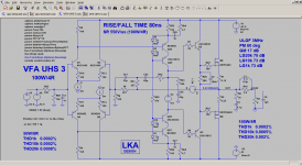
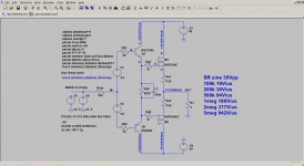
This is the same circuit but input stage is CFA.
Vmos Super CFA OIAC
And here you agreed, Ck3 is a Cherry cap.
Vmos Super CFA OIAC
This is the same circuit but input stage is CFA.
Vmos Super CFA OIAC
And here you agreed, Ck3 is a Cherry cap.
Vmos Super CFA OIAC
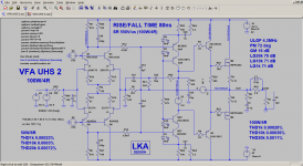
I did not notice that it has so small value, does it really play any important compensation role, you can have stray capacitance of similar value?
Ck3 and Ck4 improve phase margin. If they have higher capacity and IPS cannot supply more current (2mA divided among 1p5 and VAS input) SR is degraded.
One solution is to double IPS CCS current or/and use floating JFET IPS which can go beyond tail current.
One solution is to double IPS CCS current or/and use floating JFET IPS which can go beyond tail current.
Attachments
Ck3 and Ck4 improve phase margin. If they have higher capacity and IPS cannot supply more current (2mA divided among 1p5 and VAS input) SR is degraded.
One solution is to double IPS CCS current or/and use floating JFET IPS which can go beyond tail current.
OK that's VFA, but why you used same value Cherry caps in CFA?
OK that's VFA, but why you used same value Cherry caps in CFA?
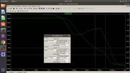
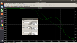
Because is optimal when considering ULGF,GM,PM. (at given TMIC+SHUNT compensation)
When Ck3 goes UP, PM and ULGF go UP, GM goes DOWN.
It has much less impact on SR comparing to VFA.
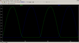
I had to slow this down to 600v / us for stability. one of Valery's designs
https://www.diyaudio.com/forums/sol...ting-ideas-1970s-ips-ops-298.html#post5666097
https://www.diyaudio.com/forums/sol...ting-ideas-1970s-ips-ops-298.html#post5666097
I had to slow this down to 600v / us for stability. one of Valery's designs
https://www.diyaudio.com/forums/sol...ting-ideas-1970s-ips-ops-298.html#post5666097
3.6mA driving current and TO92 devices. enough for sine20k 30Vp, not 600V/us.
above sine100k 30Vp significant cross conduction
KSA1381 , KSC3503 are a bit slower and shift the phase. 3.6mA is the driver idle current
both can peak around 200mA. you are correct with TO-92 devices sustained 500khz full swing drive will cause them to melt. The 0.1uf cap and 3906 bias transistor prevent cross conduction.
with the 22pf caps removed, this circuit will drive 2.2k to 40v p-p at 20mhz.
both can peak around 200mA. you are correct with TO-92 devices sustained 500khz full swing drive will cause them to melt. The 0.1uf cap and 3906 bias transistor prevent cross conduction.
with the 22pf caps removed, this circuit will drive 2.2k to 40v p-p at 20mhz.
3.6mA driving current and TO92 devices. enough for sine20k 30Vp, not 600V/us.
above sine100k 30Vp significant cross conduction
The specialty of Lichtstark's front-end design - high-precision current mirrors (asymmetric - providing some gain).
As a result, Lichtstark's VAS is driven by current, increasing "speed", linearity, and immunity to external noises.
KSA1381 , KSC3503 are a bit slower and shift the phase. 3.6mA is the driver idle current
both can peak around 200mA. you are correct with TO-92 devices sustained 500khz full swing drive will cause them to melt. The 0.1uf cap and 3906 bias transistor prevent cross conduction.
with the 22pf caps removed, this circuit will drive 2.2k to 40v p-p at 20mhz.
Cordell DAPA FE page 236: 32mA driving current required for one pair IRFP240/IRFP9240 at conditions: 40Vp, 4R, 100V/us
from KSC1845 DS
Absolute Maximum Ratings
Ic 50mA
Ib 5mA
Stresses exceeding the absolute maximum ratings may damage the device. The device may not function or be opera-
ble above the recommended operating conditions and stressing the parts to these levels is not recommended. In addi-
tion, extended exposure to stresses above the recommended operating conditions may affect device reliability. The
absolute maximum ratings are stress ratings only. Values are at T A = 25°C unless otherwise noted.
I made the board capable of taking the 1381,3503 drivers but found that the circuit is more stable with the 992, 1845 drivers. Lichtstark is less susceptible to cross conduction because of the 0.1uf cap placed between the emitters. This becomes close to a short between the gates at high frequencies. the shut off speed of the drivers will determine bias drift as the frequency increases. since Lichtstark is biased around 8v any increase will show up as significant cross conduction. there is no bias difference ( 7.95v) between full output at 40hz as compared to 20khz sine.
Your analysis shows about 0.35A of cross conduction which is about right any bias drift as well as slower mosfet shutoff times are heightened. Keep in mind the "cross conduction" bias current is set at 150 - 200 mA
Your analysis shows about 0.35A of cross conduction which is about right any bias drift as well as slower mosfet shutoff times are heightened. Keep in mind the "cross conduction" bias current is set at 150 - 200 mA
Last edited:
it's TMIC (Transitional Miller Input Compensation)
see
Linear Audio | your tech audio resource
or DAPA second edition
see
Linear Audio | your tech audio resource
or DAPA second edition
it's TMIC (Transitional Miller Input Compensation)
see
Linear Audio | your tech audio resource
or DAPA second edition
I see. The connection is the inverting input, not base of the VAS.
- Status
- This old topic is closed. If you want to reopen this topic, contact a moderator using the "Report Post" button.
- Home
- Amplifiers
- Solid State
- Ultra high speed VFA 500V/us