Hi all,
CFA is fast. VFA can be too. It is all about compensation.
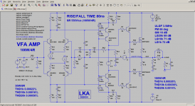
Following amp is a quite simple VFA concept, compensated by TMIC, Cherry and shunt. It behaves like CFA, rise time is constant at any output level, ca 80ns. Of course, it is not engineered to withstand these high speed edges for long time. (maybe few seconds and cross conduction kills it).
The simulated distortion is also very good indeed")
Clipping is nice, no sticking.
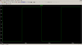
Square wave test - no overshoots.
Without output coil is stable up to 4R ll 50nF
CFA is fast. VFA can be too. It is all about compensation.
Following amp is a quite simple VFA concept, compensated by TMIC, Cherry and shunt. It behaves like CFA, rise time is constant at any output level, ca 80ns. Of course, it is not engineered to withstand these high speed edges for long time. (maybe few seconds and cross conduction kills it).
The simulated distortion is also very good indeed
Clipping is nice, no sticking.
Square wave test - no overshoots.
Without output coil is stable up to 4R ll 50nF
Attachments
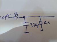
vfa desigins need input capacitor minumun 330pf
Why ? low pass filter ? yes, of course
I've submitted conceptual diagram, not the final amp schematic. Many vertical mosfet designs don't use boosted rails for the IPS. I always use when making a real amp.
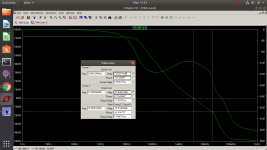
attached: LG-LoopGain and CLG-ClosedLoopGain
Attachments
Dear LKA,
kindly post the .asc file as a learning exercise for newbies.
--gannaji
here you are
Attachments
Why ? low pass filter ?
When the finger touches the input, it burn output zobel or speaker
Attachments
Last edited:
Why ? low pass filter ?
When the finger touches the input, it burn output zobel or speaker
try to touch it in simulator. what will happen ?
anyway, this is a CFA KILLER circuit ... STOCHINO KILLER, at least
Last edited:
lets do some simple math:
Slewrate = I / C
assume VAS current =+/-10mA and total VAS loading capacitance=20pF then
SLR = 1e-2/2e-11 = 500V/us.
I doubt that in reality the VAS load incl buffer inputs and pcb-traces is only 20pF. In any case this will be the bottleneck. Maybe you have drastically to increase bias current capability to reach your goal. Good luck!
btw - I do not get the reason of the hype about CFA. At least slewrate is limited by the VAS, not the input stage. And some bandwith can be achieved with both topologies.
Last edited:
lets do some simple math:
Slewrate = I / C
assume VAS current =+/-10mA and total VAS loading capacitance=20pF then
SLR = 1e-2/2e-11 = 500V/us.
I doubt that in reality the VAS load incl buffer inputs and pcb-traces is only 20pF. In any case this will be the bottleneck. Maybe you have drastically to increase bias current capability to reach your goal. Good luck!
btw - I do not get the reason of the hype about CFA. At least slewrate is limited by the VAS, not the input stage. And some bandwith can be achieved with both topologies.
VAS current is not limited to the exact level. Standing current is 8mA and it can swing up to 50mA. As I wrote, this is not designed for steady high speed at full power, it can withstand short bursts.
Show me design which can do full power 500kHz/sine for several hours. (Winfield's amp ?)
I do not know any, but I do not focuse in that direction.VAS current is not limited to the exact level. Standing current is 8mA and it can swing up to 50mA. As I wrote, this is not designed for steady high speed at full power, it can withstand short bursts.
Show me design which can do full power 500kHz/sine for several hours. (Winfield's amp ?)
I do not know any, but I do not focuse in that direction.
OK. What is the VAS standing current when DIYAUDIO guys present their 200-500V/us CFA amps ? What transistor they use for VAS and drivers when driving MOSFETs ? What is the driver standing current ? 10mA per mosfet pair? is it enough for that speeds ?
Last edited:
try to touch it in simulator. what will happen ?
anyway, this is a CFA KILLER circuit ... STOCHINO KILLER, at least
I tried so many similar amp, (experience)
For my knowledge these ultra-hi speed amps mostly are based on a fully symmetrical design with "unlimited" VAS peak current similar to yours.
This is generally true. If there is not enough current (or it is limited in some way) to charge compensation capacitors, slew rate is also limited. In the case of MIC/TMIC the key components are: VAS current, Ck1-Ck2, Rf/Rg.
In all cases the stability is the most important factor. Not THD, not SR.
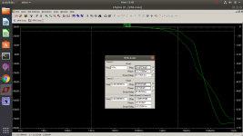
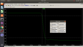
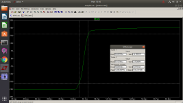
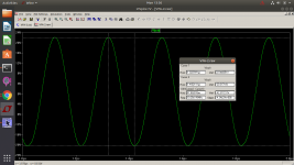
Attached graphs: (no input filter, load 4R)
clipping 20k
square wave 10k 56Vpp
rise/fall time
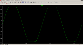
sine 5MHz (input drive to 56Vpp/1kHz)
Attachments
Hi all,
CFA is fast. VFA can be too. It is all about compensation.
Following amp is a quite simple VFA concept, compensated by TMIC, Cherry and shunt. It behaves like CFA, rise time is constant at any output level, ca 80ns. Of course, it is not engineered to withstand these high speed edges for long time. (maybe few seconds and cross conduction kills it).
The simulated distortion is also very good indeed
Clipping is nice, no sticking.
Square wave test - no overshoots.
Without output coil is stable up to 4R ll 50nF
I don't see any Cherry, could you elaborate it?
I don't see any Cherry, could you elaborate it?
Ck3,Ck4
This is generally true. If there is not enough current (or it is limited in some way) to charge compensation capacitors, slew rate is also limited. In the case of MIC/TMIC the key components are: VAS current, Ck1-Ck2, Rf/Rg.
In all cases the stability is the most important factor. Not THD, not SR.
Attached graphs: (no input filter, load 4R)
clipping 20k
square wave 10k 56Vpp
rise/fall time
sine 5MHz (input drive to 56Vpp/1kHz)
Are these real measurements?
Best regards
Ck3,Ck4
1.5pF? I don't see this as Cherry compensation.
- Status
- This old topic is closed. If you want to reopen this topic, contact a moderator using the "Report Post" button.
- Home
- Amplifiers
- Solid State
- Ultra high speed VFA 500V/us