Evenharmconics, definitely sounds like a cross channel,ground loop.
Before fitting the HBR’s , you can start by rerouting the wiring in your amp. Focus on minimizing the loop area formed by the 0V supply to the amp modules, the internal signal screen. If you listen through some headphones (after the amp is powered up and assume you have no DC offsets) you will quickly find the noisenull points.
Before fitting the HBR’s , you can start by rerouting the wiring in your amp. Focus on minimizing the loop area formed by the 0V supply to the amp modules, the internal signal screen. If you listen through some headphones (after the amp is powered up and assume you have no DC offsets) you will quickly find the noisenull points.
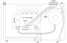
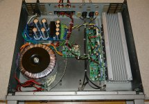
I decided to try rewiring in my other amp first. Attached image is the actual layout of the amp. It's made from an old amp chassis I picked up cheap so the locations of certain parts are restricted. I do hear buzz/hum from speakers when source is connected but silent when disconnected.
Instead of ground wire from AC-0-AC to chassis, is ground wire from speaker gr out to chassis ground a better idea?
Instead of ground wire from AC-0-AC to chassis, is ground wire from speaker gr out to chassis ground a better idea?
Attachments
"Instead of ground wire from AC-0-AC to chassis, is ground wire from speaker gr out to chassis ground a better idea? "
All the rule says is that there can be one and only one connection to the chassis - this means that the safety earth and the 0V of the PSU must go to the same point.
Here are some suggestions:-
1. Tightly bundle (I'd twist them altogether) the amplifier 0V wire with the AC secondary wires and then around the transformer on the LHS and then to the chassis ground. This minimizes the loop area.
2. The wires from the pots to the PCB must be tightly twisted together - use 2 core screened cable if you can because will guarantee minimal loop area. Also do this for the wires from the rear panel to the pots. Any loop area here will pick up noise and cause a crops channel ground loop.
3. Keep the input signal wires well away from the AC secondary wires.
4. HBR's will help
5. I would try bonding the input grounds together where they come into the chassis. This will trap any cross channel ground loops inside the amplifier and prevent them from flowing out to the source and back again.
6. Once you have done this, go back and experiment with the AC secondary + 0V to Ground cable dressing to make sure you have found the noise null point. Take a look at the 'Headphone' trick in the presentation on ground loops (link below - I think is about slide 60 or so).
7. If try try tmuikku's trick, and the noise goes away, its indicative of a cross channel ground loop problem - but points 1-6 should get you amplifier nice and quiet.
8. Make sure your input connectors and your speaker returns are NOT making contact with the chassis - if they are, you will have an earth loop.
The layout you have shown is not optimal - you have the input connections from the rear panel going to the volume control pots which are then going to the amplifier board and crossing over the AC secondary wires which are carrying very high current pulses at 120 Hz. Lots of opportunity there for noise pickup. Ideally, I would have turned the PCB around by 180 degrees - this would have meant you would not have had to cross over power, output and signal wires
Last edited:
There has been some progress, I think. Since I was already soldering HBR on one board when you posted the above, I decided to try the other channel which hasn't been touched. The following images are the culprit, I think.Evenharmconics, definitely sounds like a cross channel,ground loop.
Before fitting the HBR’s , you can start by rerouting the wiring in your amp. Focus on minimizing the loop area formed by the 0V supply to the amp modules, the internal signal screen.
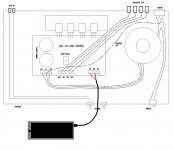
All ground connection to power supply board may have been causing the common impedance coupling (page 44 of your power point). So I relocated all other ground to star ground at the "chassis" and put a wire from power supply board ground to star ground. No buzz/hum when the source input is connected! I'm not sure if this is because only one channel is powered up and may change if the other channel is installed. I'll see how it goes.
Attachments
If the main ground going to the 0V connectors on your PSU is not 'T' d off from the 0V connecting the filter caps, then you will have common impedance problems and noise.
If this indeed is the case, then what you have done by 'T-ing' off the capacitor 0V junction is isolate your system ground from the capacitor charging ground this will have reduced the noise accordingly.
If this indeed is the case, then what you have done by 'T-ing' off the capacitor 0V junction is isolate your system ground from the capacitor charging ground this will have reduced the noise accordingly.
Progress.
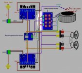
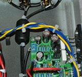
I rearranged input wires (black), DC supply wires (yellow & blue) and speaker wires (black & red). It did reduce buzz/hum quite a bit. It's surprising how much of difference the rearrangement of wires can make. It's good now but not as good as I would like. There still is faint buzz/hum when I put my ears closer than 6 inches to speaker driver. Can something in the picture be changed to make it quieter?
I rearranged input wires (black), DC supply wires (yellow & blue) and speaker wires (black & red). It did reduce buzz/hum quite a bit. It's surprising how much of difference the rearrangement of wires can make. It's good now but not as good as I would like. There still is faint buzz/hum when I put my ears closer than 6 inches to speaker driver. Can something in the picture be changed to make it quieter?
Attachments
Try this: Remove ground leads between the amps and PSU. Place a short wire connecting the two amp together. Connect in the middle of this wire a second wire to your PSU / star ground. Doing this decreases the voltage difference between the amp boards. A better option could be to move the star to between the amp boards. If there is no improvement, you can always put everything back.
I would have placed the speaker leads more to the right, away from the transformer. Connect PE to the chassis where it enters. All these measures may help. It is difficult to predict.
I would have placed the speaker leads more to the right, away from the transformer. Connect PE to the chassis where it enters. All these measures may help. It is difficult to predict.
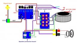
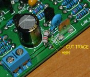
Hum breaker resistor fixed it. I didn't want to modify the board but that's what it took. I had to cut / scrape off little bit of trace on the board and solder a 12 Ohm resistor across it. No more buzz / hum! However, now I hear faint radio reception from speakers. Now onto RFI cure method...
Do you have proper electrical connection between all chassis panels? Sometimes paint / powedercoating prevents electrical connection between panels = poor faraday cage. How are the input wires again, shield goes to amplifier ground or chassis ground? Can't quite see from the picture if the input wires are coaxial or shielded twisted pair. If coaxial, ignore the question.
Can't quite see from the picture if the input wires are coaxial or shielded twisted pair. If coaxial, ignore the question.
Last edited:

There are two filters that need to be installed for RFI
1. A 1-2 nF ceramic cap from the signal ground right at the input connectors to the chassis at the point of entry. The cap leads should be no more than 1 or 2 cm long - the shorter the better
2. A series mode filter Pi in line with the signal plus. I usually use 220 Ohms and 1 nF or 1 k and 220 pF. The Both work very well. The cap is returned to the signal ground and not the chassis ground. Ideally you want this also at the input connector(s) but more often than not they end up on the amp module PCB
This should kill any RFI and will have no effect on the audio signal.
Last edited:
I've heard radio reception through my active speakers (Behringer Truth 82030A for desktop computer) but cured it with ferrite bead around the line level cables which is located very close to vent openings at the back cover of speaker. Can the same work in this case too? I happened to have a few spare ferrite beads.

- Status
- This old topic is closed. If you want to reopen this topic, contact a moderator using the "Report Post" button.
- Home
- Amplifiers
- Solid State
- Pesky 120Hz Buzz / Hum From Speakers